Arduino based EVSE/Charging point
UPDATE: IMPORTANT! If you decide to take on this project, it's strongly recommended to update bootloader on your Pro Mini board. Pro Mini boards have a bug in bootloader code and can't handle WDT (watch dog timer) resets correctly. Solution is very simple. Please use UNO bootloader, which works perfectly fine with Pro Mini boards and has no such bug. Once you update your Pro Mini with UNO bootloader, you must always chose UNO board in Arduino IDE or Xloader settings when uploading the code. This is a link to video with all instructions, to those who don't know how to do this: https://youtu.be/JH6zq_3Et-I. And here you can find WDT test code. Ifyoualready built this project, please do the bootloader update and download the latest DIY EVSE firmware.
FOR TESLA MODEL 3 OWNERS! It was reported that MODEL 3 vehicles trows a fault code with my DIY EVSE. Please use 680 Ohm resistor for R1 instead of 1 KOhm. This fixes the issues.
There are loads of open source DIY EVSE/Charging point projects on the web. Best known OpenEVSE. So I was thinking for a while to try OpenEVSE project myself. But after studying it a bit, I realized I don't need all the stuff that OpenEVSE project offers. For example in-built GFI protection is not necessary in Germany and UK where I spend most of the time as all permanently installed charging points must be protected with external RCD. Stuck relay detection circuit might affect external RCD, so this function also has no use to me. I only wanted a very simple charging point that is safe enough to use but not too complicated, to have ability of changing maximum charging current and be able to make it of the bits I already got or can acquire easily. So instead of doing OpenEVSE I decided to try and do my own charging point with a help of OpenEVSE project. I used charging state detection and PWM signal generation code of OpenEVSE project to save my time. Also it shares same PWM signal generation schematic with first version of OpenEVSE.
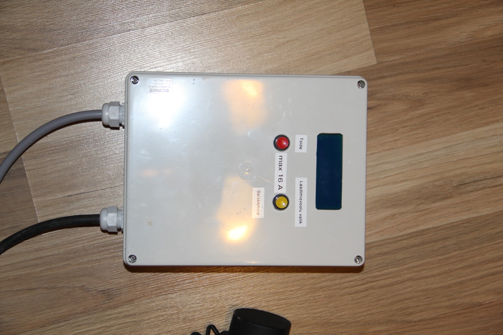
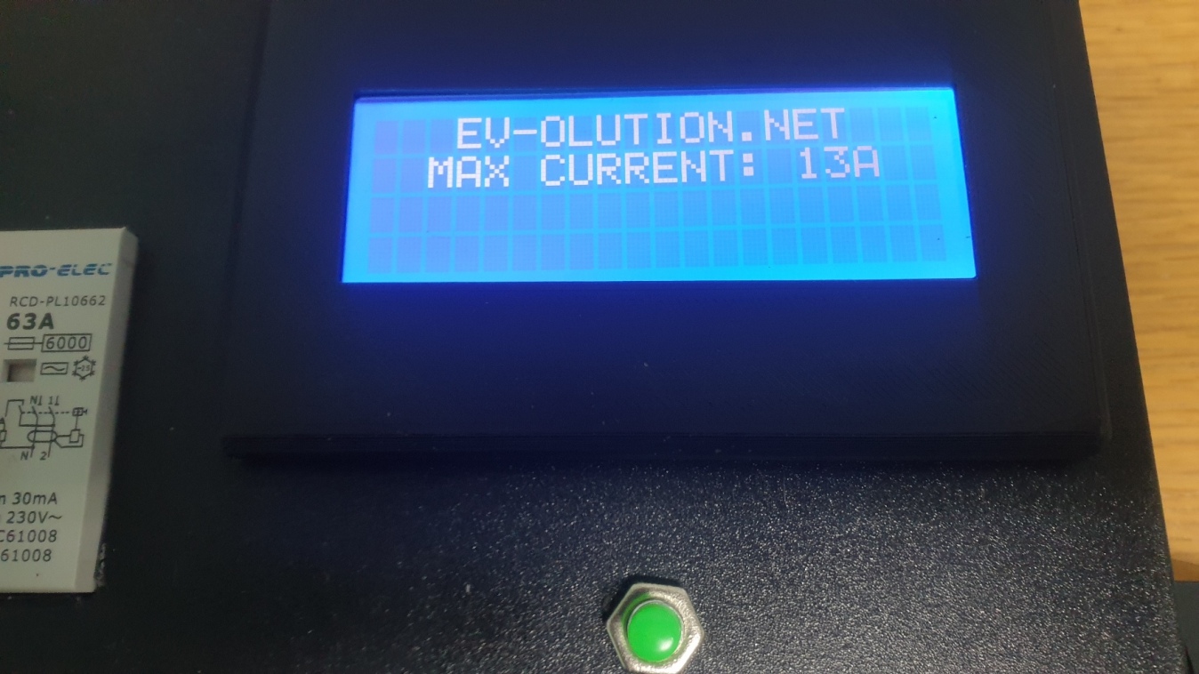
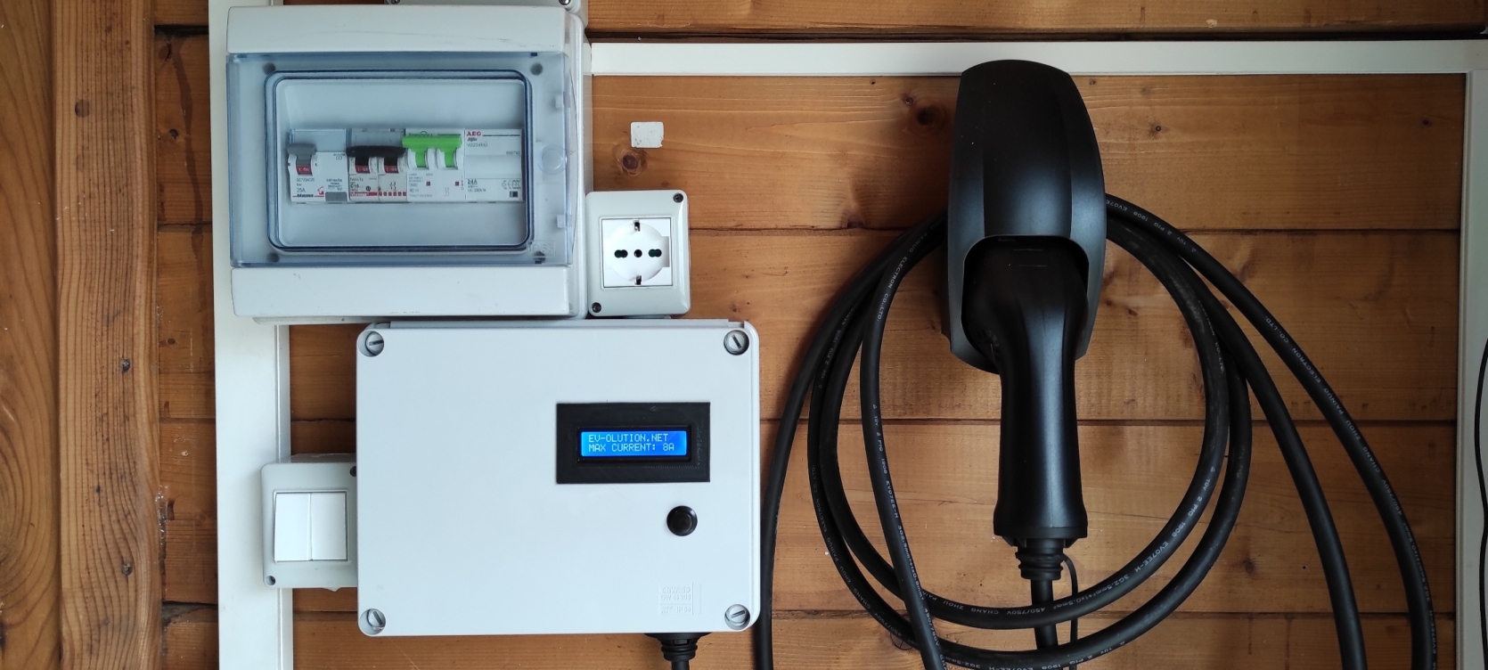
So after making my own charging point and using it successfully for few months to charge my Nissan LEAF, I decided to share it. It's not completely open source project, at least not the code for microprocessor. I am sharing it in a hex format, so you can't modify it. You are free to use it for personal projects. But it's made so that when there is no vehicle connected it shows EV-OLUTION.NET on the display. The charging current is set by pressing and holding a button. It is saved in Arduino internal EEPROM, so it will stay same even if the power supply was disconnected or interrupted. Display shows active charging session time and energy consumed. Please note, that energy consumption is calculated only by maximum current set in microcontroller and the charging session time. So it's only correct if your vehicle is consuming the same current as chargers set maximum current and the supply voltage is stable enough. For example I get close consumption readings to real consumption only if I set 16A or less for my 2011 Nissan LEAF and charging it only to 80%. So please don't expect it to be very accurate. I only made it so, because there was some unused space on display while charger is in charging state. So instead of having unused space I decided to write a little code for theoretical energy consumption calculation, just for fun...
This is a list of parts you will need:
U1 - Mean Well PT-45B power supply (or similar with DC output: 5V, 12V and -12V. You can even use old computer PSU)
U2 - Arduino Pro Mini 328 5V/16MHz
U3,U4 - I2C 16x2 LCD
U5 - LF353 Operational Amplifier
PB1 - Push button
T1,T2 - 2x Transistors 2N2222A
D1,D2 - 2x Diodes 1N4148
TVS - TVS Diode P6KE16CA
R1 - Resistor 1kOhm
R2 - Resistor 200kOhm
R3 - Resistor 100kOhm
R4 - Resistor 56kOhm
R5,R6 - 2x Resistors 10kOhm
R7,R8 - 2x Resistors 470Ohm
C1,C2 - 2x Capacitors 0.1uF
K1,K2 - 2x Relays 40A 12V
Cable with a Type 2 or Type 1 connector (depending which one you need)
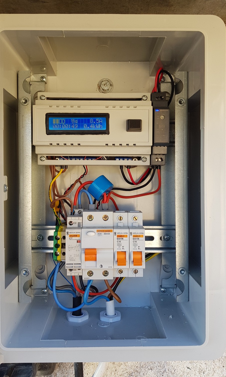
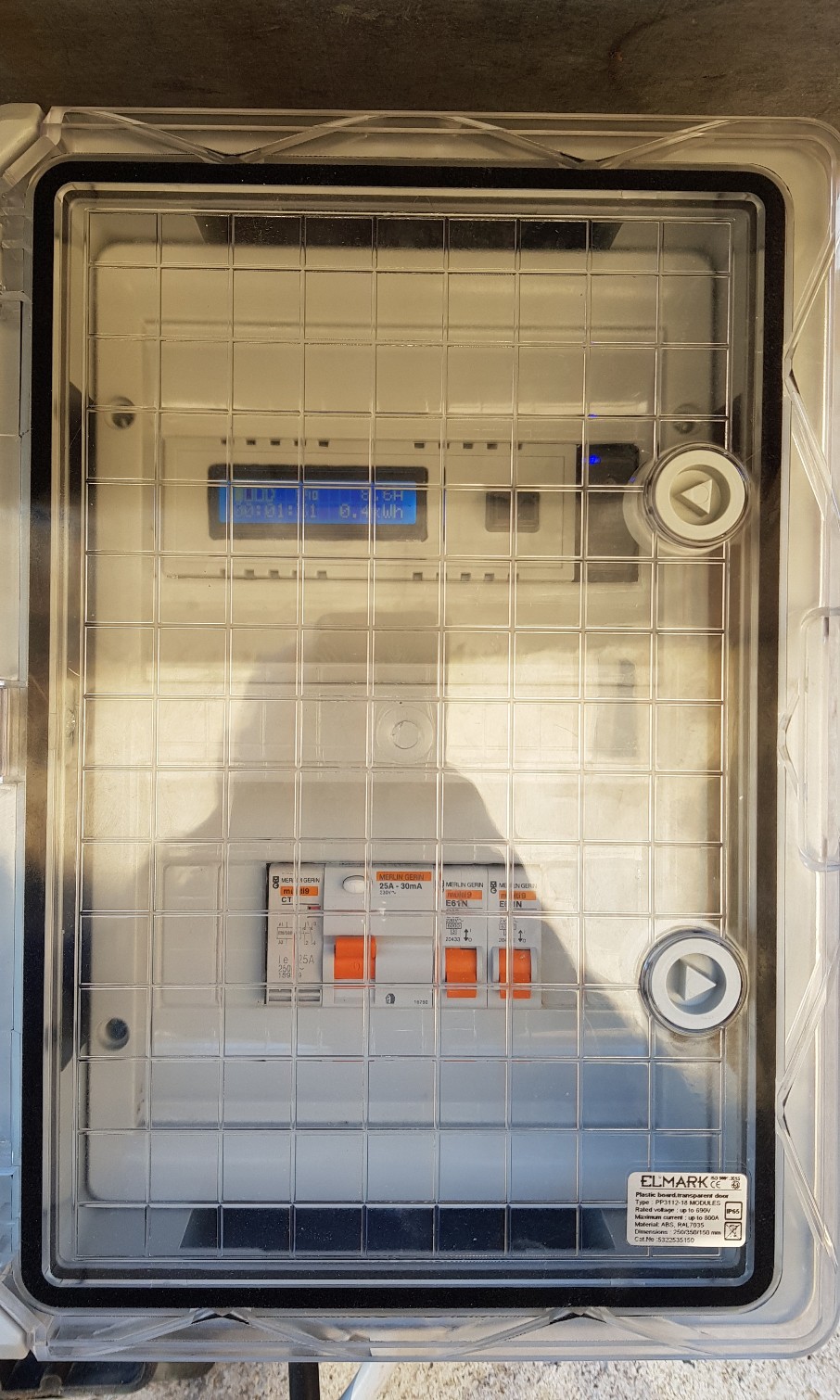
Some kind of enclosure with cable glands and power supply cable
If you want custom made PCB that suits similar project please >click here< to find out more. Please note that if you buy PCB or PCB kit, it comes with a firmware, that can monitor real current and energy consumption (single and three phase), also can be used to build non tethered charging point as it got Proximity Pilot detection circuit integrated and can be used with a WiFi module to control and monitor EVSE. To find out more please >click here<
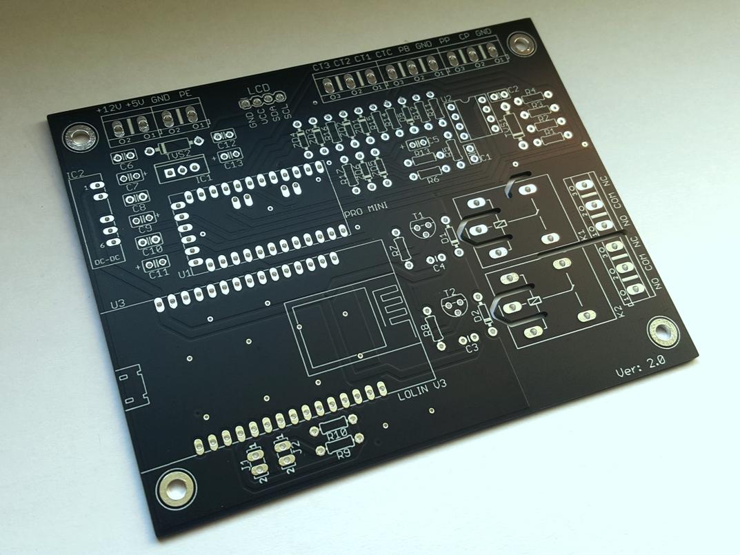
If you still chose to build your own PCB this is a diagram that will work with the firmware from this page. If this diagram looks to complicated for you, then I would strongly advice not to take on this project and learn basic electronics first.
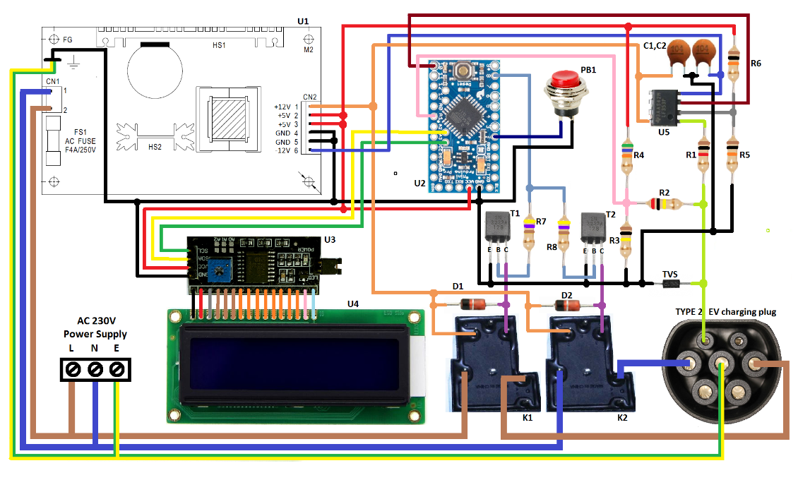
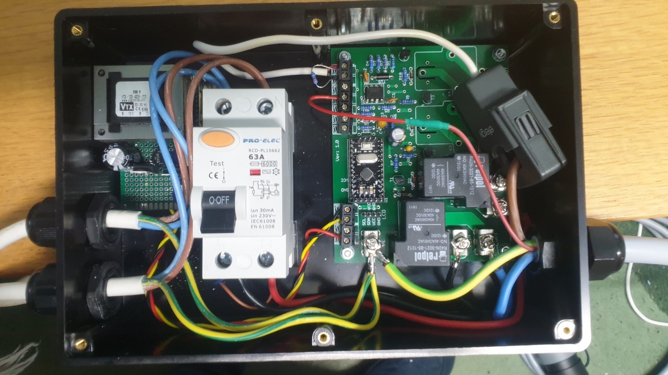
As you see I have used PT-45B power supply. There are two main reasons. First is the cost. It is very cheap and comes with 2 year warranty. Second reason, it has loads of integrated protections and filters. Few to mention: surge protection, short circuit protection, overload protection, over voltage protection, wide input voltage range 90 ~ 264VAC. Also I found that output voltage is very stable. You can use different power supply or even PSU from your old computer, as it got 12V, -12V and 5V outputs. You can even use DC/DC inverters or something else, but I personally prefer PT-45B option.
Below you will find Arduino firmware in HEX format and instructions how to upload it to your Arduino. Current setting range: 6A to 32A. Voltage for energy consumption calculation: 230V

|
DIY_EVSE_FREE_v1C_wdt-on.rar Size : 9.791 Kb Type : rar |
You can use standard USB to TTL adapter to upload HEX file to your Arduino. Connect it exactly same as you would do while using Arduino IDE. Just instead of using Arduino IDE use program called Xloader. Make sure you use only Xloader version 1.00, newer versions requires special adapter. If you having difficulties finding Xloader v1.00 please contact me. Download my HEX file, open it in Xloader, chose Nano*(ATmega 328) (*chose UNO if you got UNO bootloader on your Pro Mini board), chose correct COM port for your adapter, connect your Arduino to adapter and press Upload. If you are using PL2303 based adapter please hold reset button on Arduino, and release it straight after you pressed Upload in Xloader. After powering Arduino for the first time you need to press button PB1 and hold it till you see at least 6A on display to set the maximum current, as internal EEPROM of your Arduino is empty and no values are stored. You can even make it as a three phase charging point. Just connect power supply feed to neutral and one of the phases. And use one of the relays to control 4 pole contactor. I have added new "soft stop" future in this firmware. If you press button while charging point is in charge state, it will stop PWM signal and after 300ms disconnects relays. Do not use this function for vehicles with Type1 charging connector as it will triggers fault code on your vehicle. This function must be used only for vehicles with Type2 charging connector.
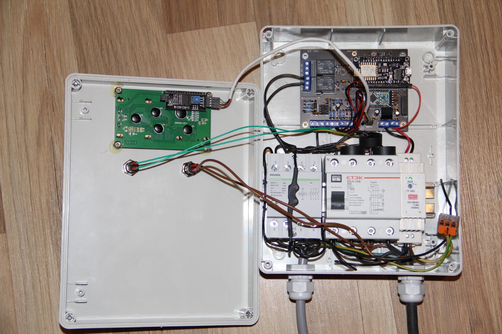
There is update on this project. This update allows user to get some parameters and readings from EVSE, and also protect it from unauthorized use. This is done by using cheap Lolin V3 board (ESP8266 based), MaQiaTTo broker and a "MQTT Dash" App for Android smartphones. To read more about this update, please > click here <.
Important: This charging point must only be connected to power supply which is protected by the 30mA AC RCD! Electrical Wiring Regulations in some countries now require 6mA DC RCD device to be installed also on EV charging points. So check your country wiring regulations. This project has no in-built RCD protection! Also please note, this project is for educational purposes only and you understand that you take all responsibility if you use it as a permanent charge equipment as it is not considered as a finished product. Also your finished project must be inspected by competent person before connecting it to mains and I will not take any kind of responsibility as I will repeat it again, this information is provided for educational purposes and must not to be used to build a final product! Also I'm not selling any charging points as a final product. So if you will see devices on sale that displays EV-OLUTION.NET on the screen, please note I have nothing to do with them. That would mean someone just using my files to profit without my permission.
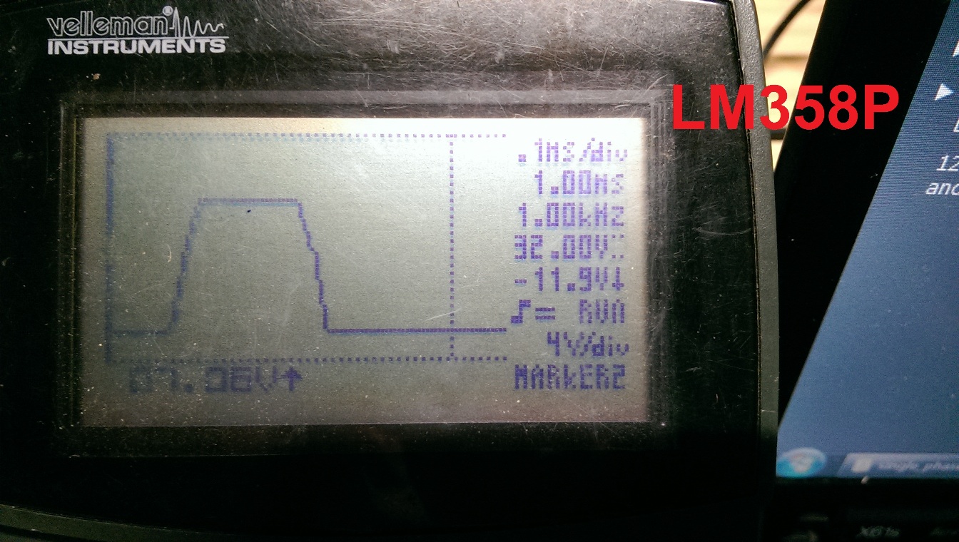
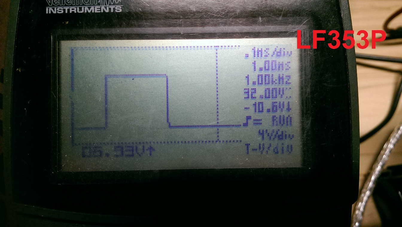
Please DO NOT use LM358P instead of LF353P !!!
Please compare the pictures below :
How it works and what you should see on the screen after you power it up, you will find in the video below. This is the short demonstration video so you can have an idea of how it looks and works when assembled. I hope you will find it useful.
Update: 10/10/2021
Power supply alternative
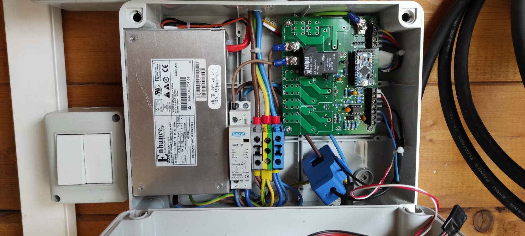
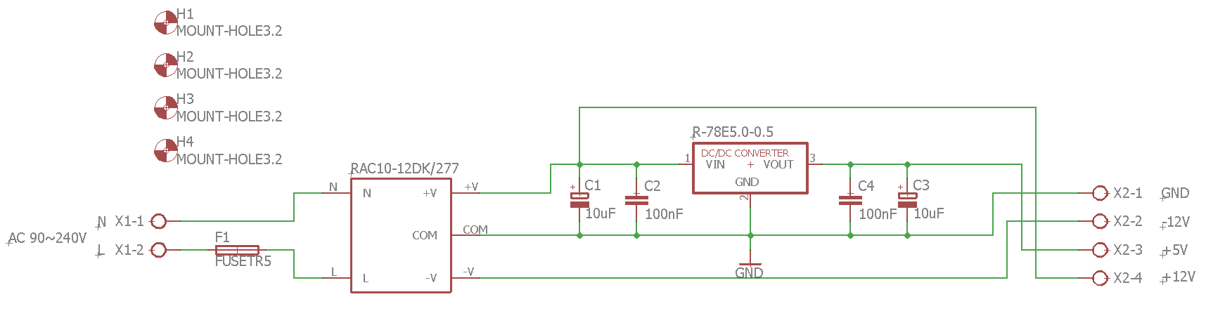
It seems that Mean Well PT-45B power supply is no longer easily sourceable. Even if you can find it sold locally, the price seems to be doubled in very short period of time. So I was looking for simple and cheap alternatives. One of such alternatives I am sharing below. It is very simple and can be built by using just a few components. Please note, that such power source is not suitable, if you are using Lolin Wifi board connected to your EVSE, as it's output is not strong enough to keep Lolin board powered up.
Part list for power supply:
AC-DC Converter - RECOM RAC10-12DK/277 (2 outputs: +12V and -12V)
DC-DC Converter - RECOM R-78E5.0-0.5 (single output of 5V 0.5A)
C1, C3 - 2x Capacitors 10uF
C2, C4 - 2x Capacitors 100nF
F1 - Fuse (TR5 type if you are using my PCB design)
X1, X2, X3 - 3x DG301 (XY306) 2 Position Screw Terminal Block (only if you are using my PCB design)
Power supply wiring diagram and Gerber files for PCB manufacturing can be found bellow:
|
|
EVSE_PSU_board.zip Size : 32.903 Kb Type : zip |
Troubleshooting:
Due to very high amount of emails from people who take on this project without needed skills and asking for my help when things go wrong, I no longer offer my support on free DIY Arduino based EVSE. I will only help people who bought PCB for this project. Most of the time in such emails people asking why for some reason "correctly" assembled device is not charging. And the reason is, that it is NOT "correctly" assembled, wrong or damaged parts used. So if your device is not working as it should, please check the list of most commonly made mistakes while doing this project. Trouble shooting other people mistakes is very time consuming, and finding a free minute is a challenge to me already:
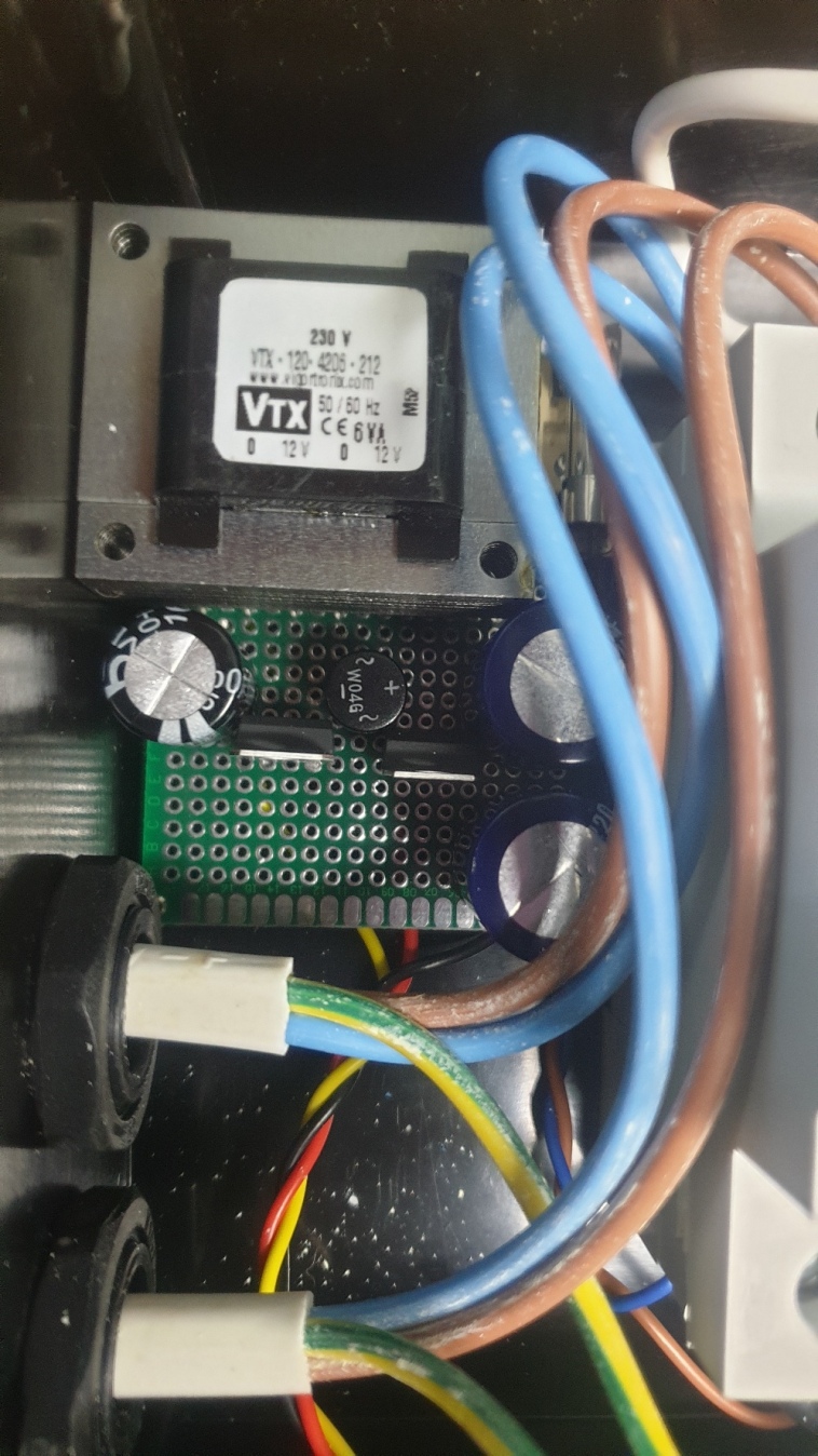
--After connecting to vehicle, nothing happens. Cause: Arduino GND or power supply GND terminal is not connected with Protective earth/ground terminal. See my wiring diagram. This is probably the most commonly made mistake. Please always connect your Arduino GND contact to Protective Earth/Ground terminal on power supply or Earth/ Ground wire that goes to charging plug.
--Vehicle trows a fault code blaming defective charging connector or incorrect signaling. Cause: If you using Type 2 connector you must make sure it has inbuilt resistor between PE and PP terminals. Just measure resistance between these terminals on your connector. It should be 200Ohm for 32A rated connector and cable, 680Ohm for 20A and 1.5kOhm for 13A.
--Intermittent charging. Cause: very low quality resistors are used with low precision. I would recommend to use only high precision resistors, probably ones with 1% tolerance. R1....R6 resistors are critical for correct operation. Also "noisy" power supply can cause same issues. Please check your power supply using oscilloscope. Some vehicles like Tesla are very sensitive to voltage instabilities and will refuse to take a charge.
--Various problems. Cause: check your PCB design few times. Even if you think it's perfectly fine, check it again.
--Nothing on the screen or displays random symbols. Cause: Incorrect Arduino board is used. My code will work only with 5V 16Mhz Arduino boards that is equipped with Atmega328 processor.
--Nothing on the screen but charging is working. Cause: make sure you are using I2C adapter with PCF8574T chip (NOT PCF8574AT !!!) and communication address of screen is set to 0x27. If you not sure how to do that, follow this link: https://www.ardumotive.com/i2clcden.html. If you using I2C adapter with PCF8574AT chip, please contact me for a new Arduino file, as the ones in this site won't work.
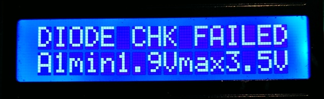
--Message "DIODE CHK FAILED" on the screen as soon as you connect to vehicle. Possible causes: Faulty/incorrect TVS. Power supply -12V voltage is less than -11V. Incorrect resistor values. Double check your design. To find out if TVS is the problem, just disconnect it. If no more error messages on screen, that means you need new/different TVS.
Having a oscilloscope is also quite handy. You can check for correct voltages on Arduino A1 analog input. You can't measure these voltages on A1 with a standard multimeter as it is PWM signal that is coming in to A1 input. If you don't have oscilloscope no stress. I compiled debug file for your Arduino, which will display A1 minimum and maximum voltages on the LCD screen. Debug file is set to 10A charging power (no adjusting is possible). Just upload it to Arduino if you having some issues. And check what voltages you see on the screen.
Debug file:

|
DIY_EVSE_DEBUG_A1.hex Size : 21.719 Kb Type : hex |
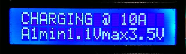
Here is how display looks, with debug file loaded to Arduino, in charging state and in diode fault state:
Arduino A1 input voltages your screen should display in various charging states:
Not connected to vehicle (no PWM) - min: 4.3V-5V; max: 4.3V-5V
Connected to vehicle (PWM) - min: no more than 1.2V; max: 3.8V-4.2V
Charging (PWM) - min: no more than 1.2V; max: 3.4V-3.7V
Vent requested (no PWM) - min: less than 3.4V; max: less than 3.4V
Diode fail (PWM)- min: more than 1.2V
© Copyright EV-OLUTION