Arduino based EVSE/Charging point PCB v2
If you want our DIY EVSE PCB kit that suits DIY Arduino EVSE project please visit our store page as we got some PCBs made. Please note that we post them only to EU countries. If you are not from EU and still want to buy our kit you can use third party delivery companies such as www.mailboxde.com. Please be aware that by using third party delivery companies you will end up paying twice for postage and sale taxes.
Although this PCB and our firmware can be used to assemble fully functional charging controller, it is not designed to be used as final product. It was designed to be used for developing purposes only! So if you decide to use it as a final product to charge your vehicle, all responsibilities and liability goes only on you. You must take all necessary certification procedures by yourself before using it as final product! We will not take any liability for damage or injury caused while using our products. As we clearly state that this project is only for developing purposes and comes as a developing sample.
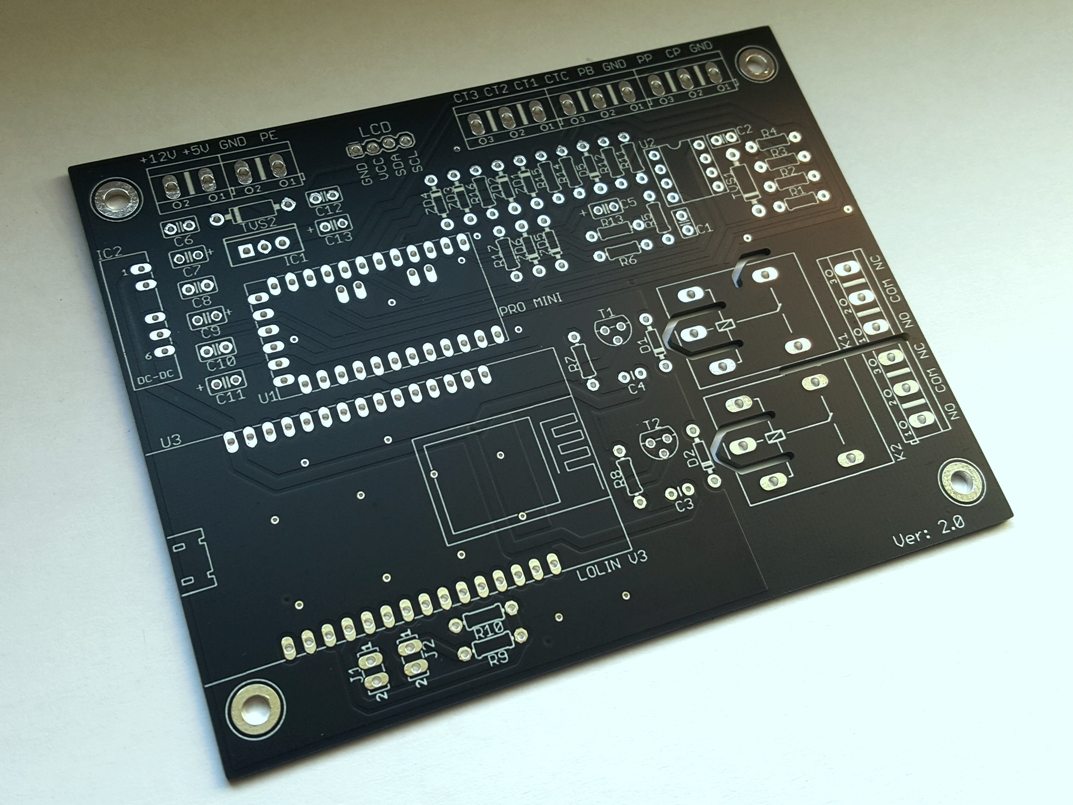
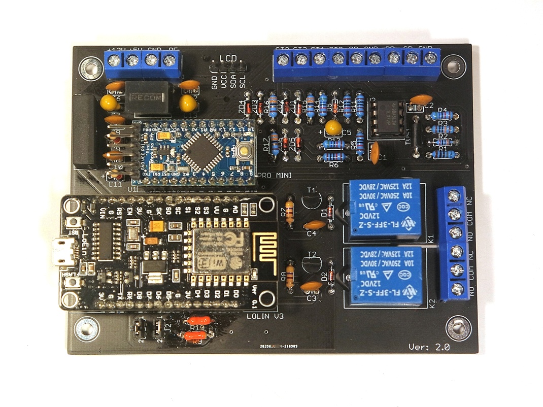
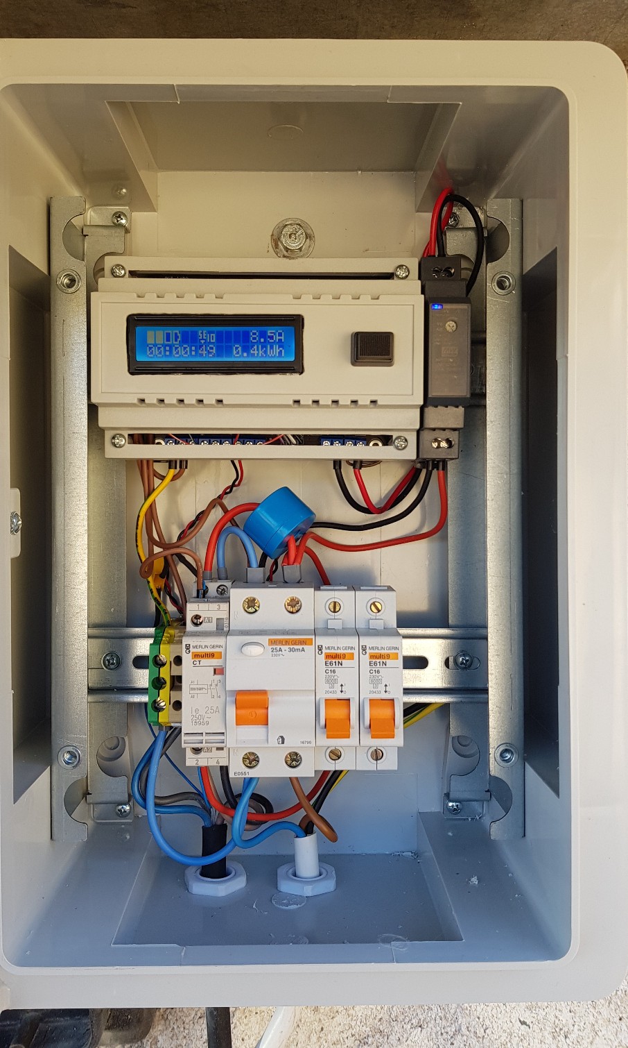
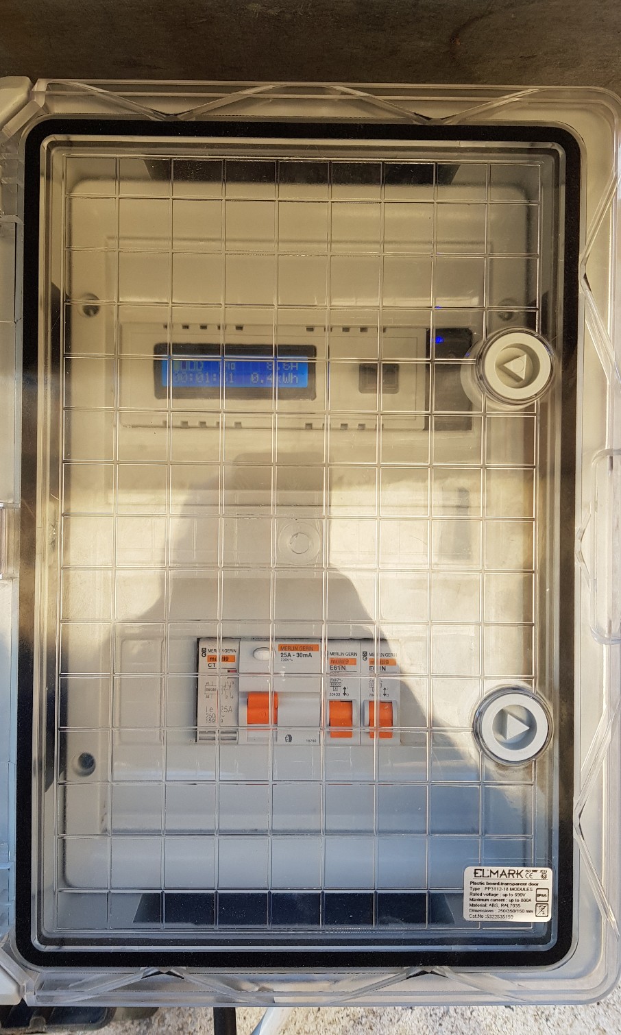
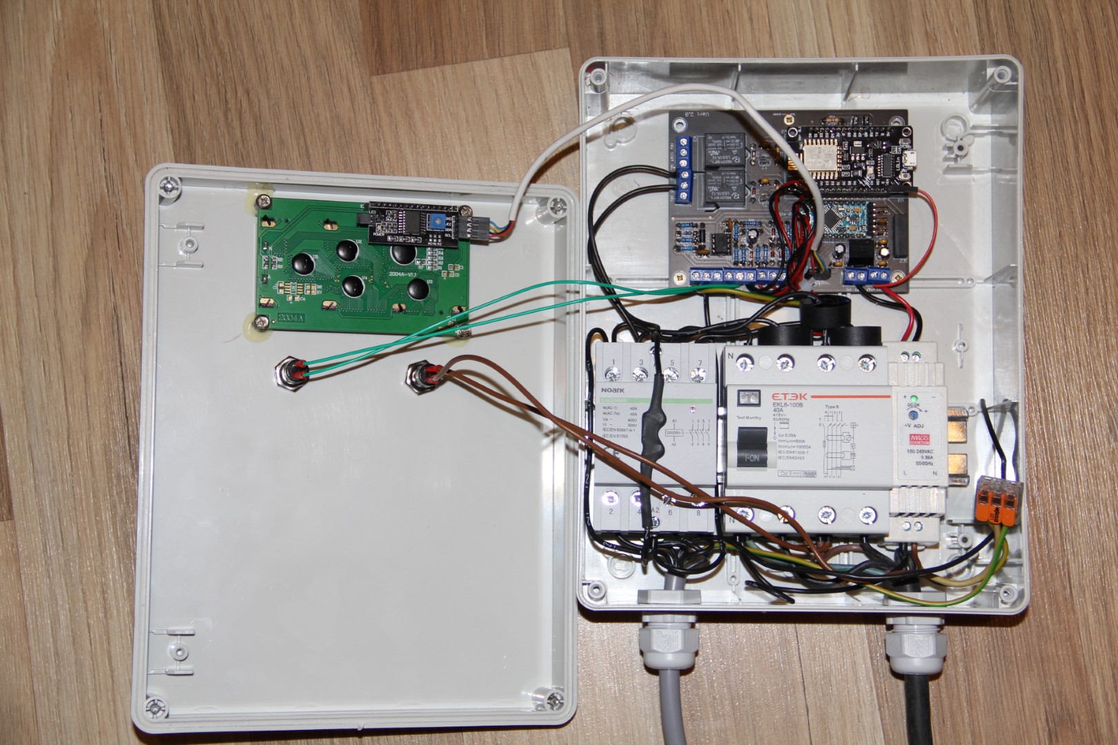
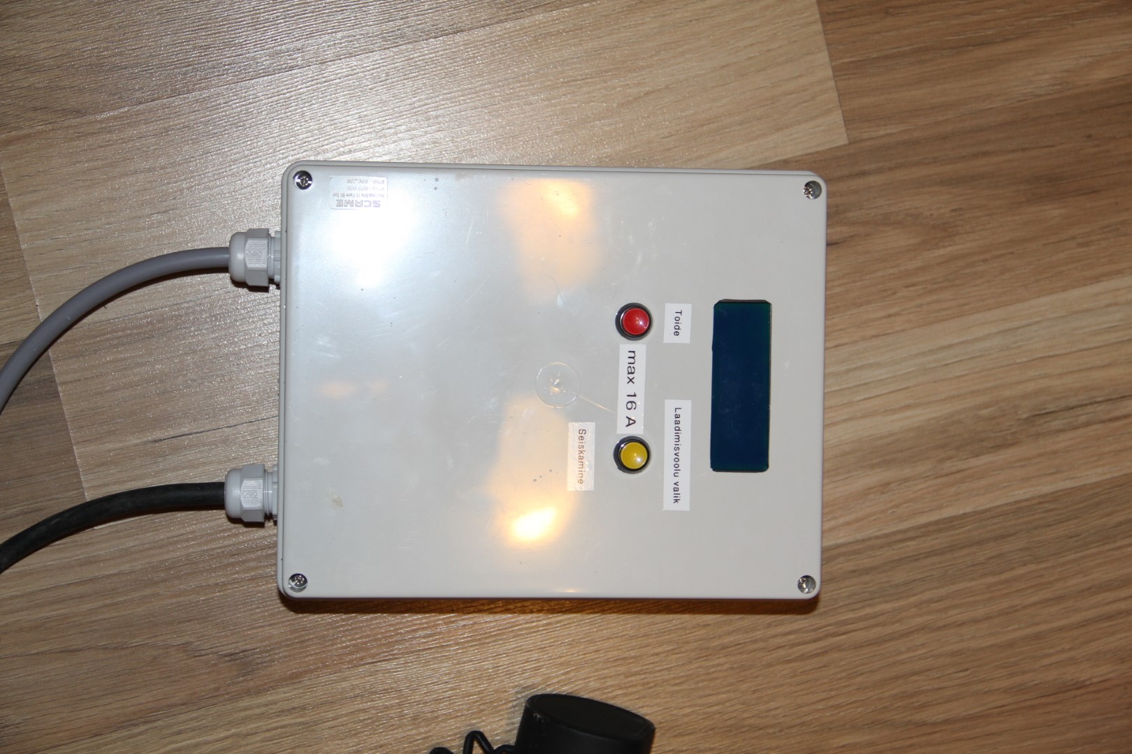
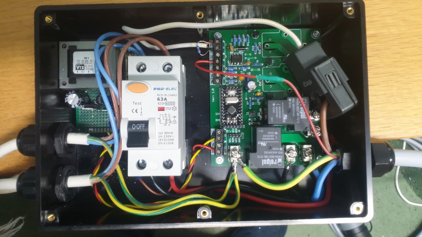
These are example pictures of DIY EVSE PCB v2.0:
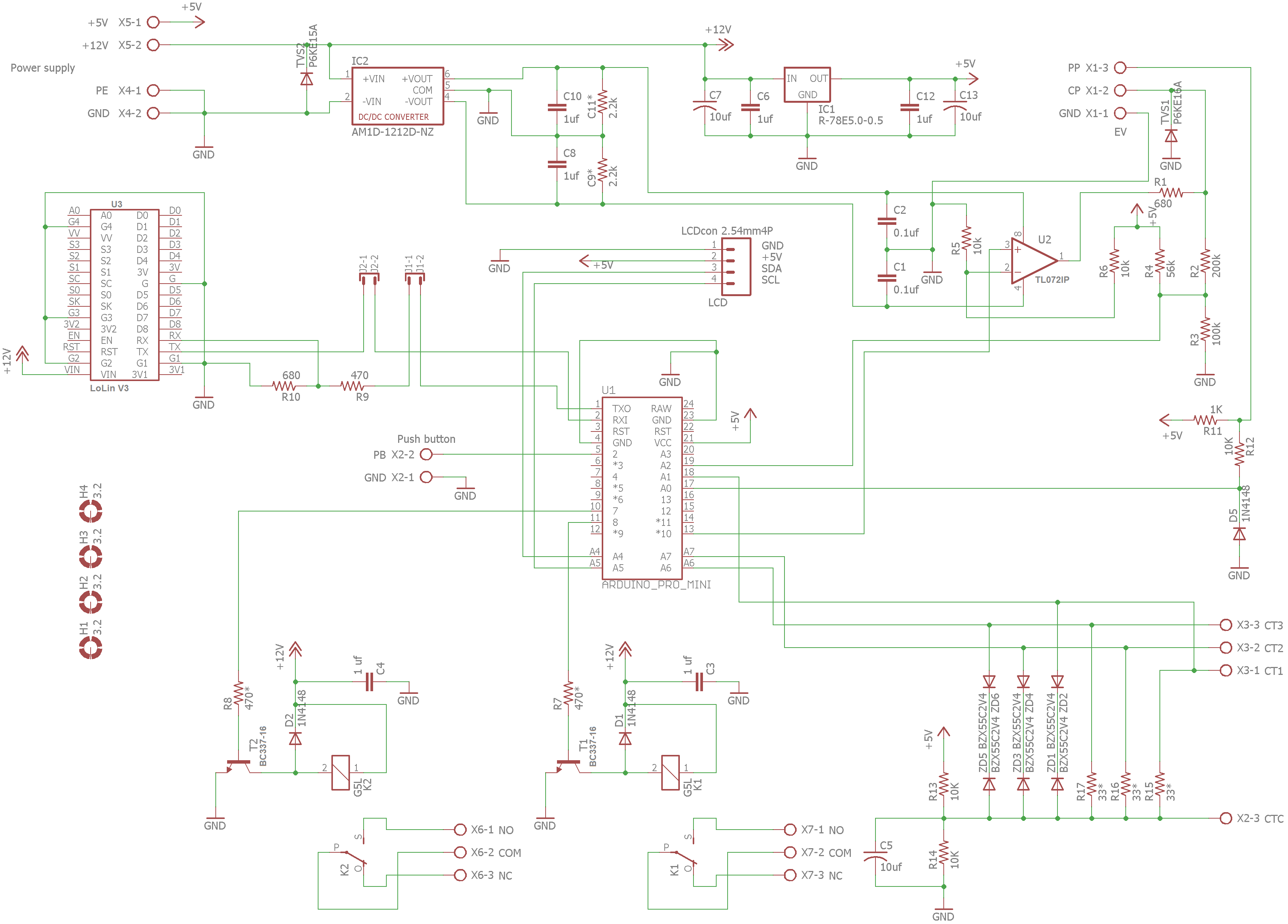
Please see Assembly Instruction Manual, Schematic and Connection Diagrams attached bellow:

|
Assembly_instruction_manual_for_DIY_EVSE_v2_c.pdf Size : 5396.666 Kb Type : pdf |

|
DIY_ARDUINO_EVSE_V2_schematic_diagram.png Size : 278.157 Kb Type : png |
|
|
V2.0_evse_diagram_a.jpg Size : 1178.529 Kb Type : jpg |
We designed it so there is absolute minimum of electronic components involved in soldering this board. V2.0 EVSE board still requires external power supply. Power supply must meet next requirements:
Output Voltage: 12V DC (must never exceed 12.8V as this will damage TVS diode!)
Output Current: at least 500mA if you choose not to use LoLin WiFi board. 1A if you are using Lolin WiFi board.
DIY EVSE V2 is designed to be used with external contactor instead of onboard high current relays. This was done to improve reliability and safety. Also cost of good quality high current relays are almost exact as contactor. So we don't really see any advantage to use PCB mounted relays anymore.
To assemble this PCB you will need good quality solder iron which is rated no less than 60W.
This PCB can be used to build single phase or three phase charging point controller. It is made to be used with Pro Mini 5V 16MHz controller board. It can monitor and display real charging current and energy consumed if used with 2000:1 ratio current transformer/sensor (three sensors for three phase version). Don't expect consumed energy to be 100% accurate as there is no voltage detection circuit integrated in this project (to keep it as simple as possible). Both, single phase and three phase versions, will have adjustable maximum charging current, diode fault detection, charging state and charging time display, possibility to stop charging by pressing button on charging point (soft stop for vehicles with Type 2 connector). PCB also can be used on non tethered charging points (non tethered means charging point with a socket), as it has proximity detection circuit integrated. It also has simple serial communication implement, so it can be used to control and monitor EVSE, if used with WiFi module (LoLin v3). PCBs are lead-free. All above functions only available if you use our latest firmware, which will be provided in non editable format. So no further modifications can be done by customer.
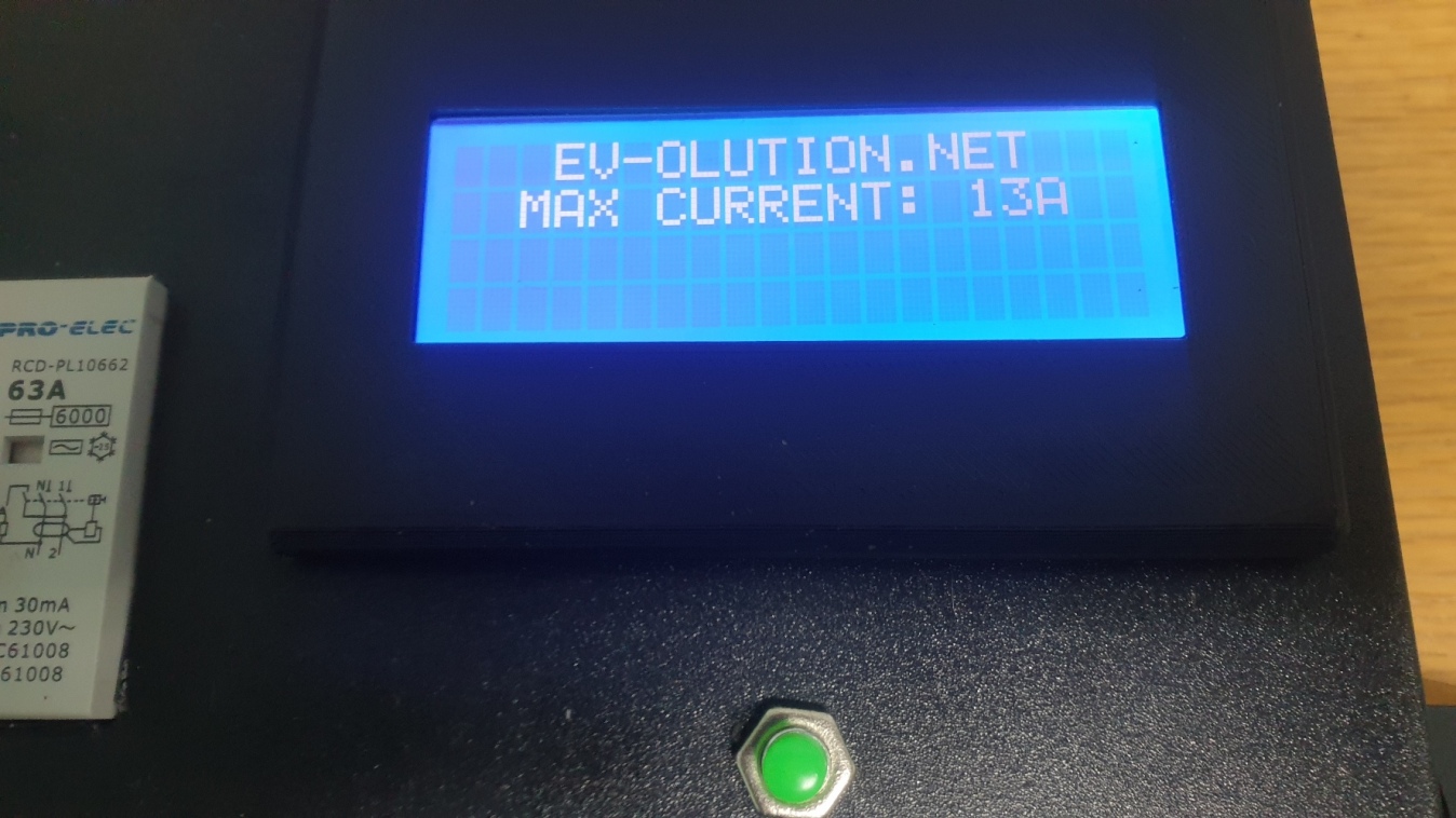
Latest firmware (non editable) for Pro Mini can be found here (password protected, only for those who bought PCB). EVSE displays "EV-OLUTION.NET" on LCD while not charging for copyright purposes.
Make sure you use only Xloader version 1.00 for uploading a firmware to Pro Mini. Newer versions require special adapter and will not work with your USB to TTL adapter. If you're having difficulties finding Xloader v1.00 please contact me.
Please don't waste your and my time asking to share my own firmware in editable format. This will never happen. There are few reasons why my code is not made as open source. First of all there are loads of similar projects with open source codes and if you really can develop a code, you probably can easily write such a simple code from scratch in no time. If you can't do it from scratch, that means you can't play with existing code, as this project involves high voltage circuit and mistakes can be fatal.
Unfortunately, there are also plenty of people who try to use other people work and time for an easy profit without even contributing to source. Or electronic students trying to grab someones work and represent it to uni as their own.
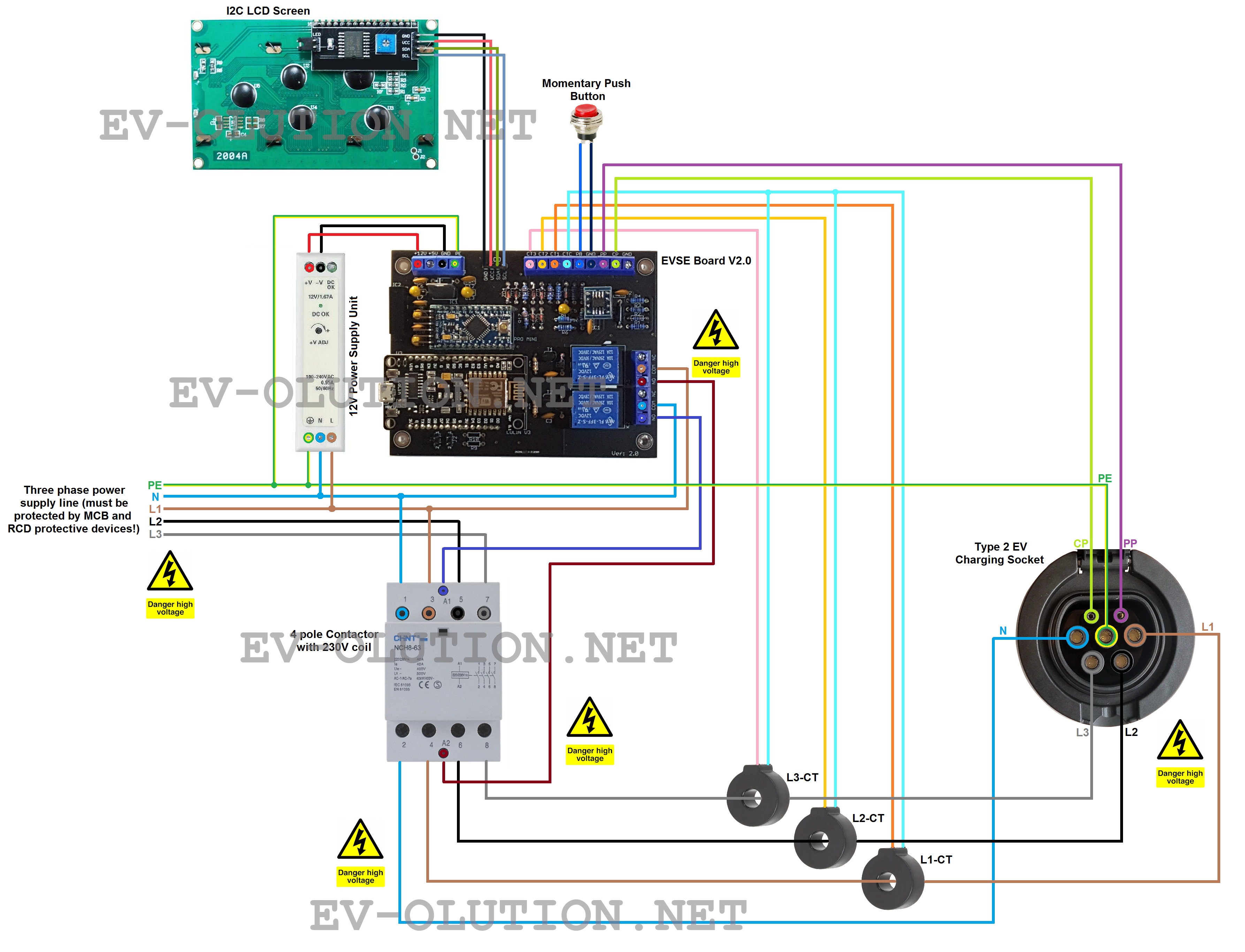
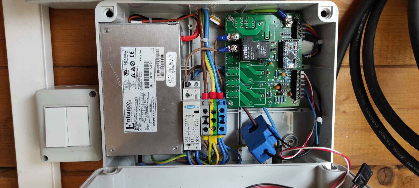
Below you will find a picture of example connection diagram:

Latest Updates and known Issues:
04/12/2021 - MaQiaTTo.com is down
It looks like maqiatto.com is down. That means your DIY EVSE project WiFi functionality will be affected and will not work while maqiatto is down. You've got few options: wait till maqiatto is up and running again, register with new MQTT broker or setup your own MQTT broker on your own computer. If you went for option two or three then you need to alter MQTT broker settings in esp8266 code (MQTT_BROKER, BROKER_PORT, MQTT_USERNAME, MQTT_KEY) and alter settings in your MQTT App (Address, Port, User Name, User Password, Client ID). If you need help with doing this, please contact us and we will guide you.
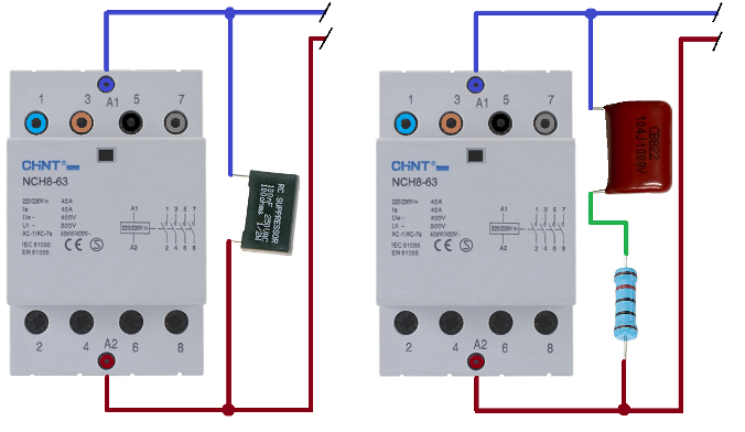
20/11/2021 - It was reported by two customers that sometimes LCD starts displaying random symbols after contactor was engaged or switched off. This is caused by EMI (Electro-Magnetic Interference). EMI corrupts data sent on I2C bus. There are few ways to prevent this from happening. First and probably the main way is to use correctly rated RC snubber connected to contactor AC coil. Although some top brand manufacturers include RC snubber in their contactor design, many cheap contactors have no RC snubber integrated in them. So you must always check contactor datasheet and see if it’s present in your contactor design. If not, or you can’t find such information, please always use additional RC snubber. Component values will vary depending on contactor coil characteristics. But usually they are 0.1 to 0.5 uF capacitor (it must be rated not less than 600 VAC) and a 20 to 200 Ohms resistor (0.5...5 Watt). Also you can choose RC snubber which has all needed components integrated in one component. RC snubber must be installed as close as possible to contactor coil terminals. See the following example picture:
Other ways to minimize EMI:
- Keep LCD and other microcontroller signal wires as short as possible. The longer they are the higher possibility that they will be affected by EMI.
- Use ferrite bead on LCD wiring.
- Use shielded wires for LCD and button switch, connecting drain wire to GND terminal on EVSE board. Note that drain wire must be kept shorter than 5cm.
- Never run microcontroller signal wires close or parallel with AC wires.
- Microcontroller signal wires should be routed as far away as possible from relays, contactor, power supply unit and other noisy equipment.
- Keep checking for firmware updates, as we plan to update our firmware with code which would reset I2C bus more often, so LCD would not be much affected even if you couldn’t eliminate EMI in your setup.
02/11/2021 - IMPORTANT!!! Anyone who chooses to use LoLin Board (not sold by us), please see the last picture attached!!! There was a report of damaged LoLin board when used with our DIY EVSE board. It's because there are some very badly designed fake boards which are completely incompatible with our design. Please check the picture and see the differences between good and bad LoLin modules. If you bought LoLin board which is marked as bad in my picture, please return it to the seller, as these are very low quality and incorrect design WiFi modules. Don't hesitate to contact us if you have any doubts about your LoLin board.
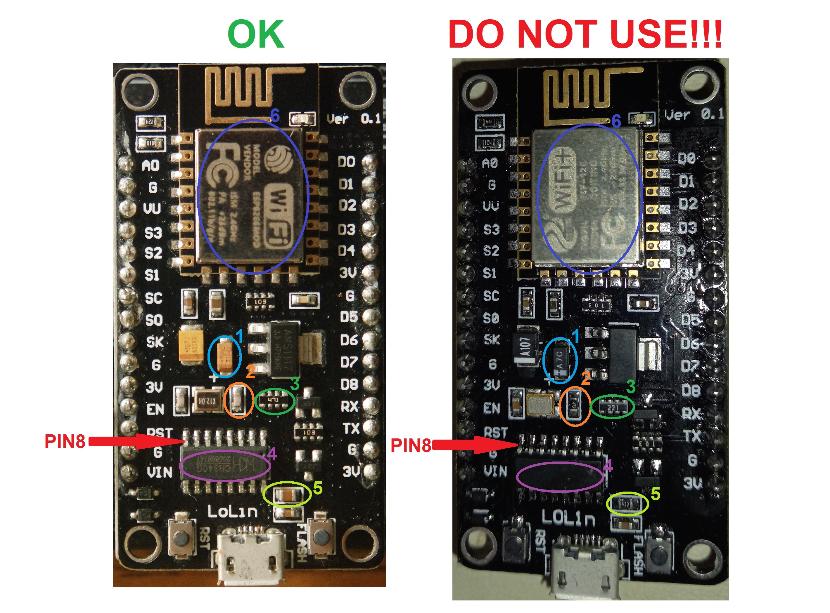
CH340G PIN8 on the left (correct) board is connected to crystal oscillator. CH340G(?) PIN8 on the right (fake) board is connected to Vin after a diode!!! This will damage fake board instantly when connected to our EVSE board! 1. Left board has correctly rated 16V capacitor. Right board capacitor is only rated to 10V! It will be damaged instantly when connected to our EVSE board!
2. Note the difference between good and bad boards. Left (good) has capacitor next to crystal oscillator. Bad one has resistor.
3. Note the difference between resistor net values.
4. On a bad board CH340G has no marking. My guess is that it's not even genuine CH340G.
5. Note the difference between components. Left board (good one) has capacitor and right board (bad one) had resistor soldered in same place.
6.Good board has ESP8266MOD WiFi module. Bad one has ASP-12E module.
If your board does not match the left board shown in this picture, DO NOT USE IT WITHOUT CONSULTING WITH US FIRST!!!
Below you will see a video with examples of how every advanced DIY EVSE firmware will look like. If you can't see video, that means you haven't accepted cookies for this website. You can try clearing your browser cache and reload my website, this time accepting all cookies. Or just follow this link: http://www.youtube.com/embed/lu_Lk8vM35Y
Video of how to access current sensor calibration screen (http://www.youtube.com/embed/XMWdDWNPO7o):
Below you will see a video with explanation how to setup your DIY EVSE to be used with WiFi board (Lolin v3). Editable firmware files for Wifi board > can be found here <:
http://www.youtube.com/embed/3gsv9lBetgs
© Copyright EV-OLUTION