Arduino based EVSE/Charging point PCB
UPDATE: IMPORTANT! If you decide to take on this project, it's strongly recommended to update bootloader on your Pro Mini board. Pro Mini boards have a bug in bootloader code and can't handle WDT (watch dog timer) resets correctly. Solution is very simple. Please use UNO bootloader, which works perfectly fine with Pro Mini boards and has no such bug. Once you update your Pro Mini with UNO bootloader, you must always chose UNO board in Arduino IDE or Xloader settings when uploading the code. This is a link to video with all instructions, to those who don't know how to do this: https://youtu.be/JH6zq_3Et-I. And here you can find WDT test code. If you've already built this project, please do the bootloader update and download the latest DIY EVSE firmware.
FOR TESLA MODEL 3 OWNERS! It was reported that MODEL 3 vehicles trow a fault code with my DIY EVSE. Please use 680 Ohm resistor for R1 instead of 1 KOhm. This fixes the issue.
If you want custom made PCB that suits DIY Arduino EVSE project please contact us or visit our store page as we got some PCBs made.
Although this PCB and our firmware can be used to assemble fully functional charging controller, it is not designed to be used as final product. It was designed to be used for developing purposes only! So if you decide to use it as a final product to charge your vehicle, all responsibilities and liability goes only on you. You must take all necessary certification procedures by yourself before using it as final product! We will not take any liability for damage or injury caused while using our products. As we clearly state that this project is only for developing purposes and comes as a sample.
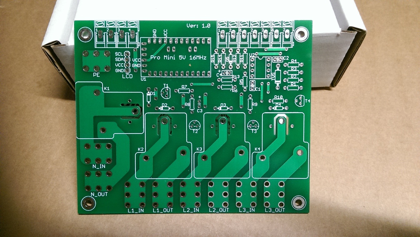
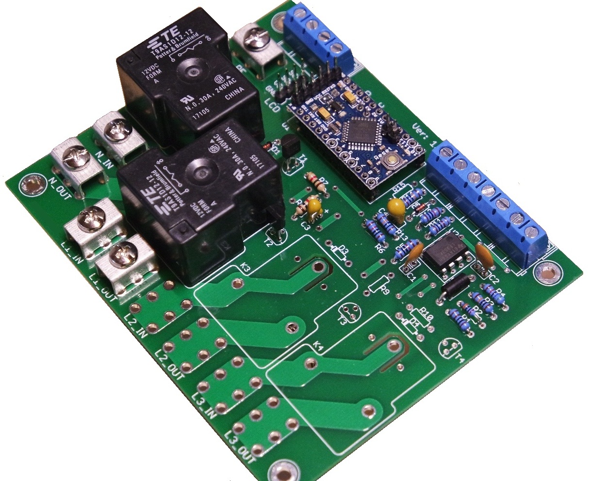
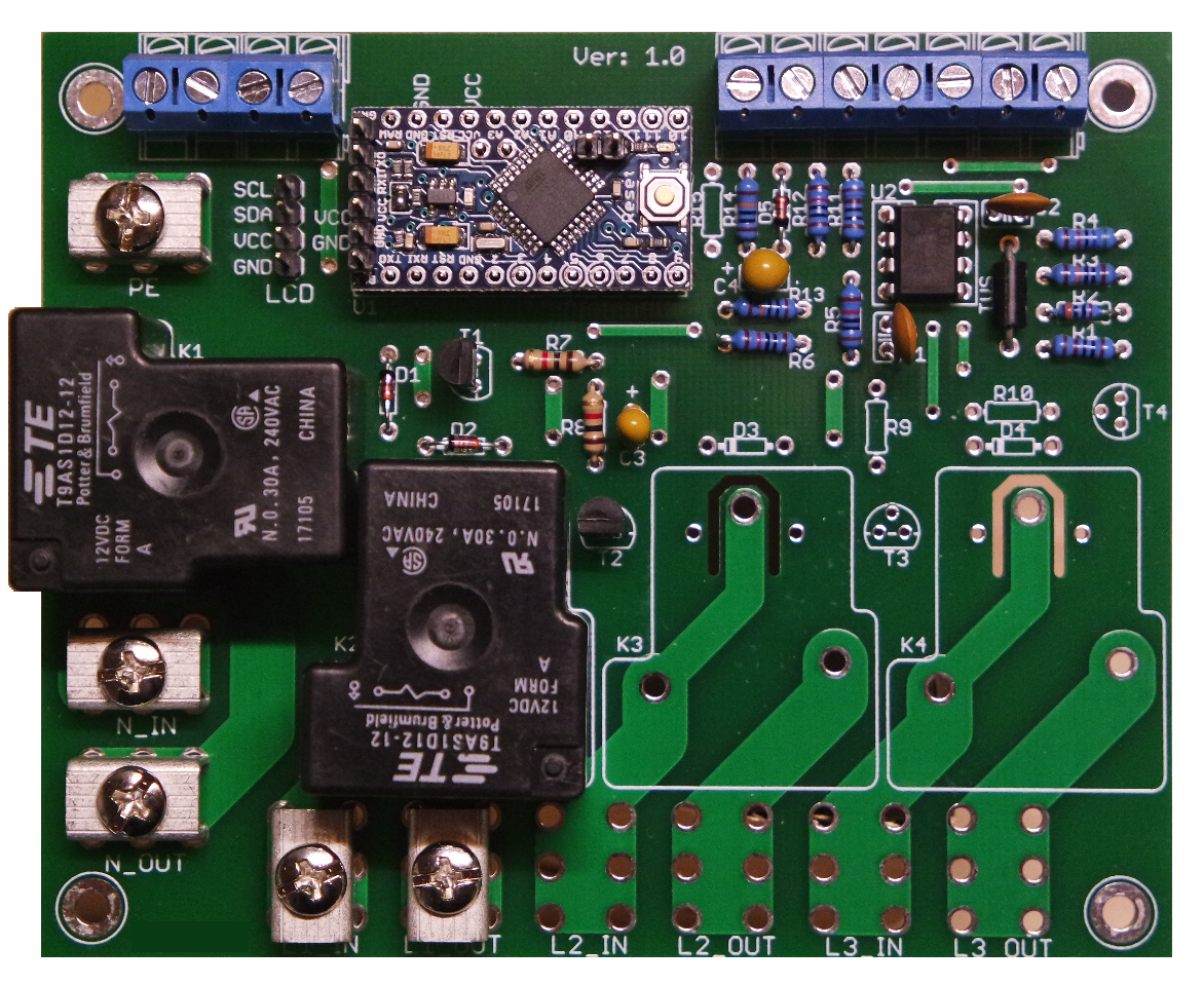
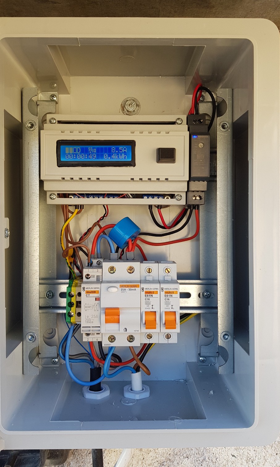
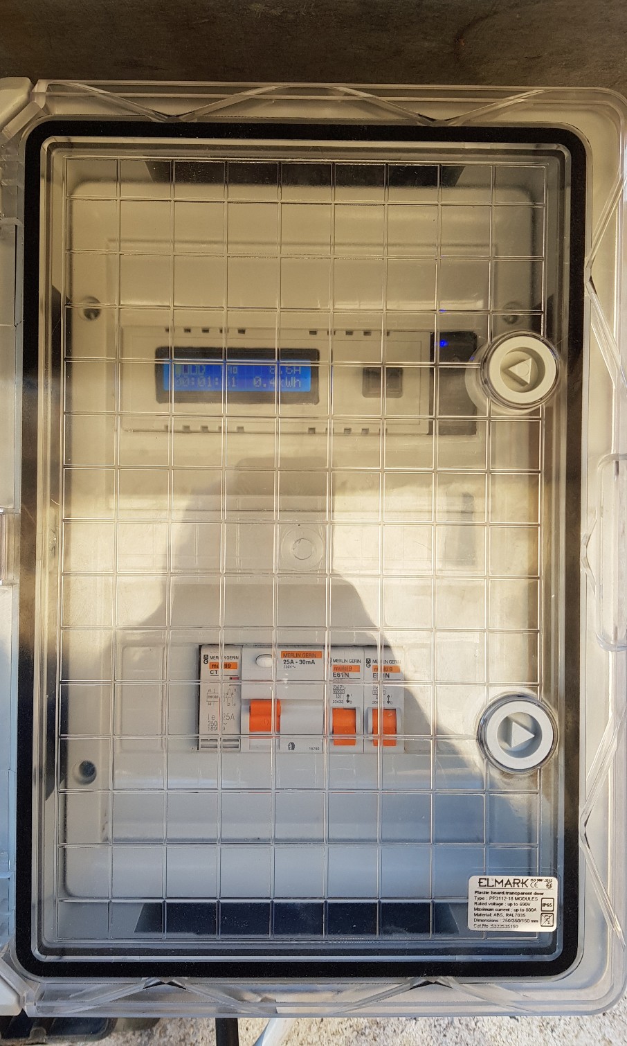
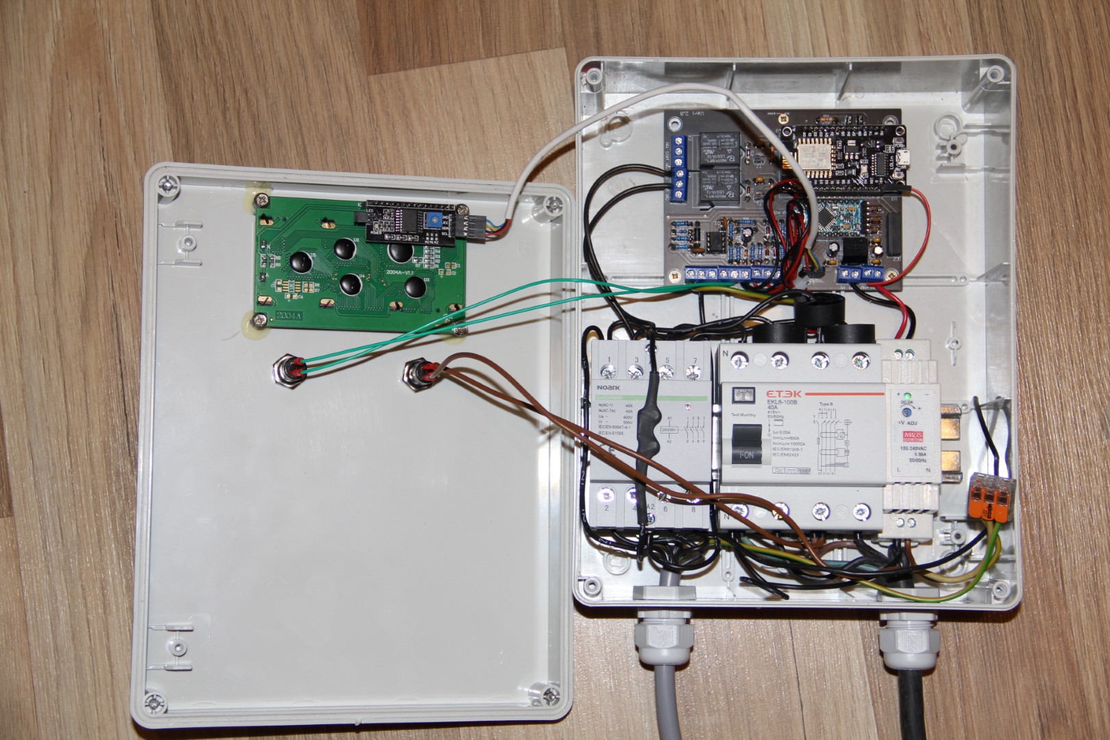
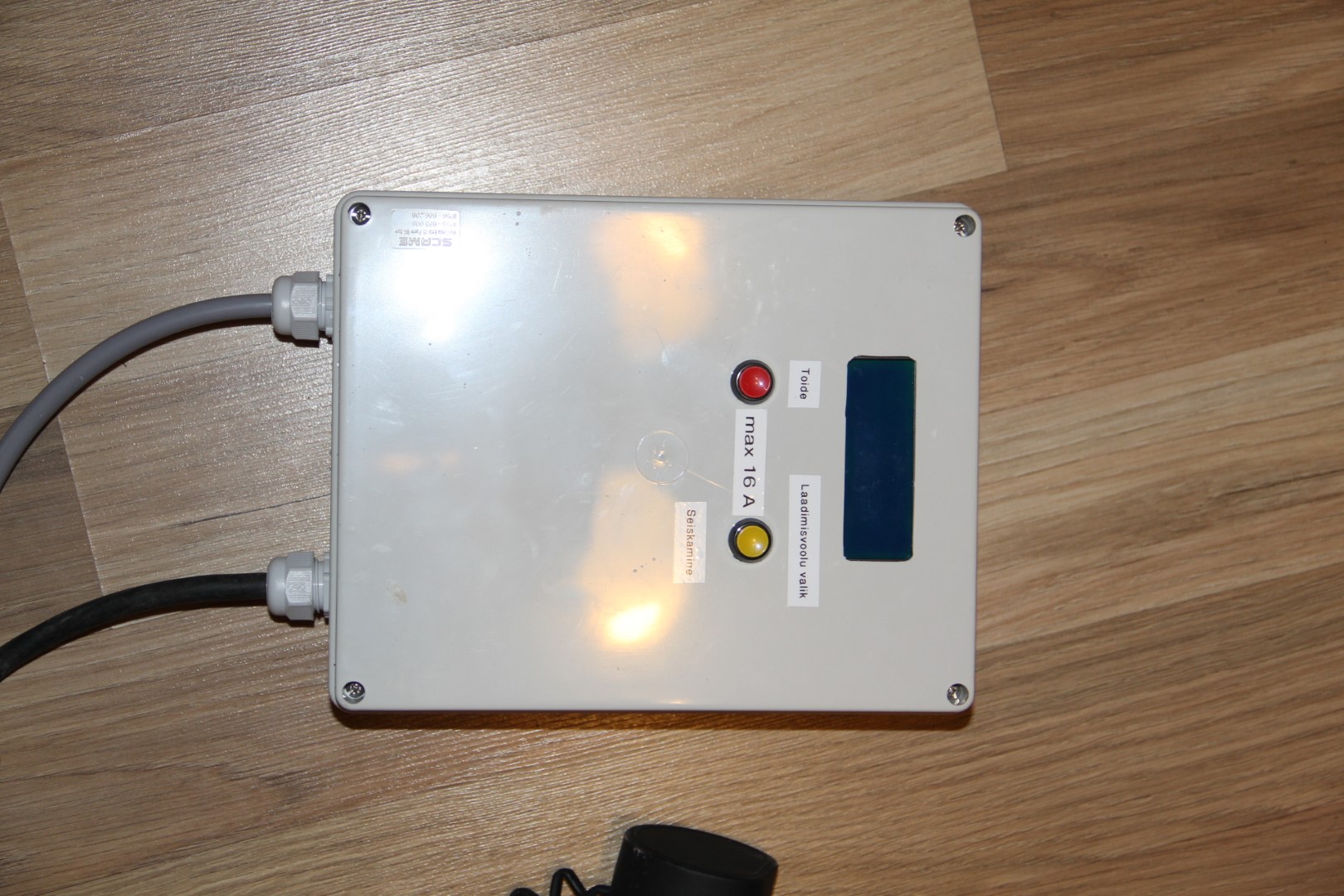
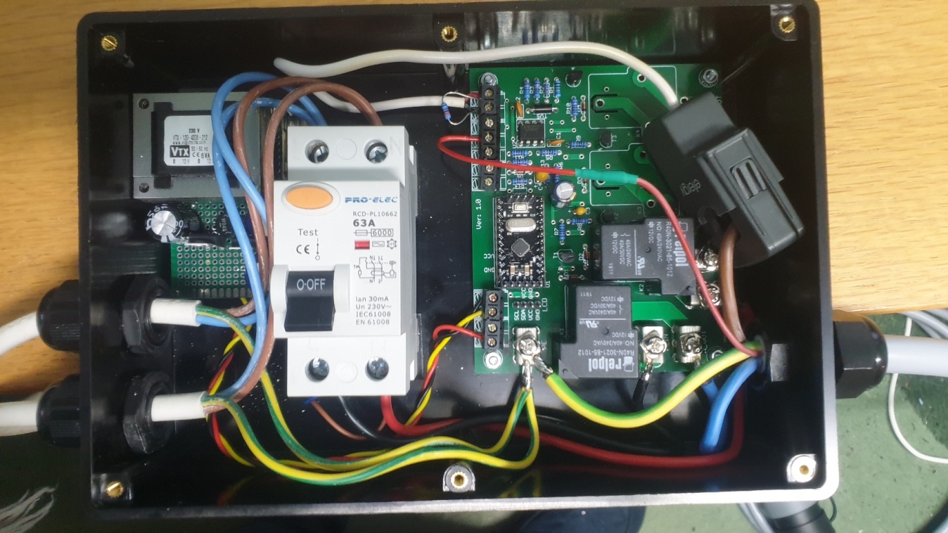
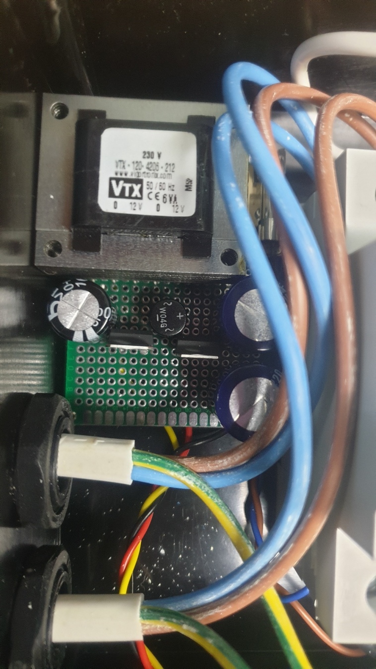
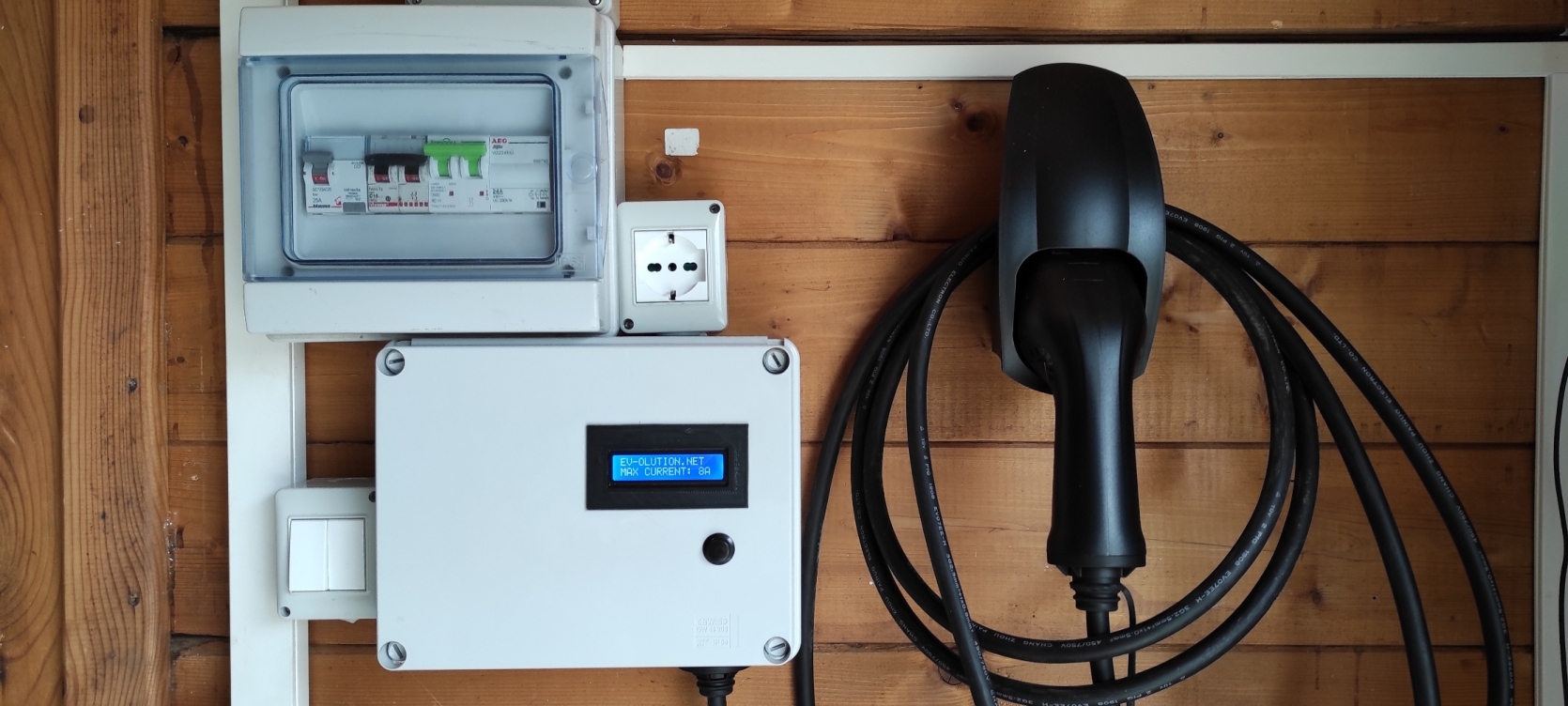
These are example pictures of PCB and assembled PCB for a single phase DIY EVSE:
We designed it so there is absolute minimum of electronic components involved in soldering this board. First version of this PCB still requires external power supply, such as Mean Well PT-45B. We made it so, because complete power supply cost less than to built it from separate components. Also PT-45B comes with various integrated protections. Which would be hard to implement in DIY power supply.
This PCB can be used to build single phase or three phase charging point controller. It is made to be used with Pro Mini 5V 16MHz controller board. It can monitor and display real charging current and energy consumed if used with YHDC SCT-013 050 (50A/1V) current transformer/sensor (three sensors for three phase version). Don't expect consumed energy to be 100% accurate as there is no voltage detection circuit integrated in this project (to keep it as simple as possible). Both, single phase and three phase versions, will have adjustable maximum charging current, diode fault detection, charging state and charging time display, possibility to stop charging by pressing button on charging point (soft stop for vehicles with Type 2 connector). PCB also can be used on non tethered charging points (non tethered means charging point with a socket), as it has proximity detection circuit integrated. It also has simple serial communication implement, so it can be used to control and monitor EVSE, if used with WiFi module (Lolin v3). PCBs are lead-free. All above functions only available if you choose to use one of my 12 different firmwares, which will be provided in non editable format. So no further modifications can be done by customer.
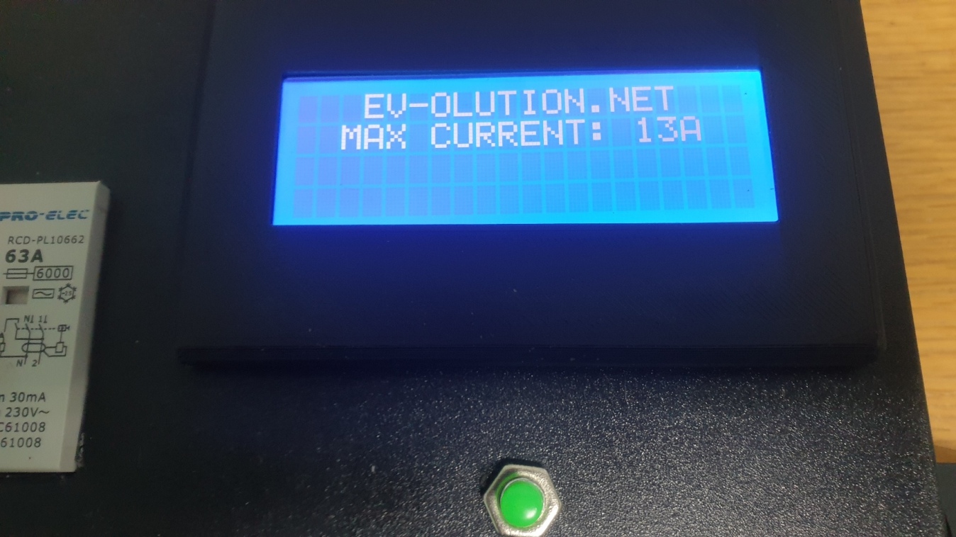
Most recent firmware (non editable) for Pro Mini can be found here (password protected, only for those who bought DIY EVSE kits). No further development is possible by user as firmware is provided in non editable format. It will have "EV-OLUTION.NET" displayed on LCD for copyright reasons.
Make sure you use only Xloader version 1.00 for uploading a firmware to Pro Mini. Newer versions requires special adapter and will not work with your USB to TTL adapter. If you having difficulties finding Xloader v1.00 please contact me.
Please don't waste your and my time asking to share my own firmware in editable format. This will never happen. There are few reasons why my code is not made as open source. First of all there are loads of similar projects with open source codes and if you really can develop a code, you probably can easily write such a simple code from scratch in no time. If you can't do it from scratch, that means you can't play with existing code, as this project involves high voltage circuit and mistakes can be fatal.
Unfortunately, there are also plenty of people who try to use other people work and time for an easy profit without even contributing to source. Or electronic students trying to grab someones work and represent it to uni as their own.
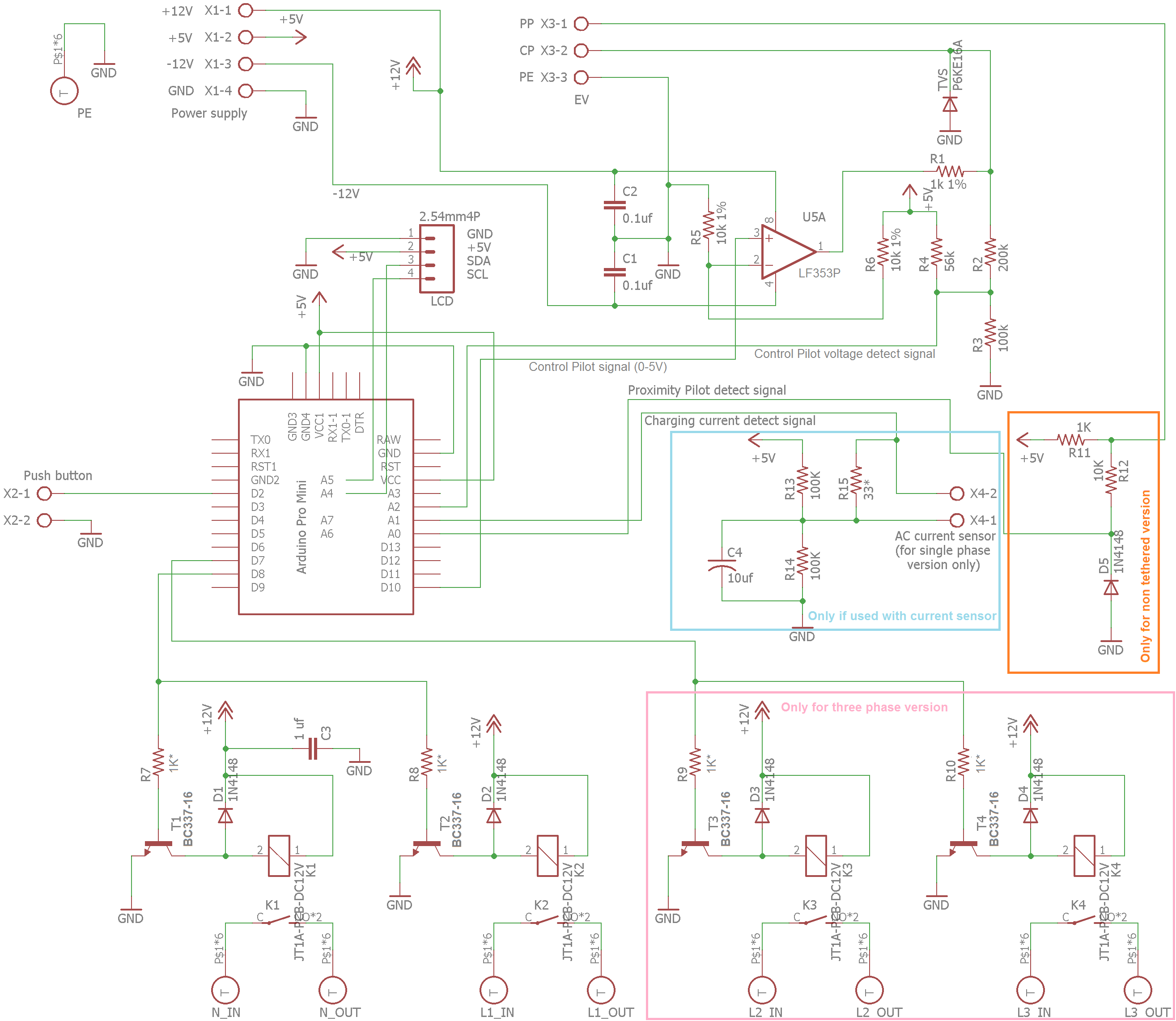
Press on the files below to download the assembly instruction manual and to view a diagram. Assembly instruction manual updated at 29/08/2021.

|
DIY_EVSE_Assembly_Manual_1f.pdf Size : 4355.891 Kb Type : pdf |

|
DIY EVSE Schematic.png Size : 227.845 Kb Type : png |
Below you will see a video with examples of how every advanced DIY EVSE firmware will look like:
Video of how to access current sensor calibration screen:
Below you will see a video with explanation how to setup your DIY EVSE to be used with WiFi board (Lolin v3). Editable firmware files for Wifi board > can be found here <:
If you can't see videos that means you haven't accepted cookies on my website. Please clear your browsers cache and reload my website again. Just this time press accept on the cookie popup window.
Mistake was done while designing V1.0 PCB, so ONLY these relays listed below MUST be used. These are 4 pin relays and they will not be affected by mistake in PCB design. DO NOT USE relays with 5 pins!
40A Relays:
R40N-3021-85-1012 made by RELPOL
HAT901ASDC12-1 made by HASCO RELAYS
NT90RNAS12CB (sealed), NT90RNAE12CB (covered)
NT90RHAS12CB, NT90RHAE12CB (40A only approved by TUV and UL! CQC approved only 30A)
AZ2150-1A-12DE made by ZETTLER
AZ2150-1A-12DEF made by ZETTLER
2027395-5 / T9VV1K15-12S made by TE Connectivity (TE)’s Potter & Brumfield (This relay will require PCB drilling as main pins are bigger than PCB trough holes)
30A Relays:
R30N-3021-85-1012 made by RELPOL
HF105F-1/012DT-1HSTF made by HONGFA RELAY
L90AS-12W made by RAYEX ELECTRONICS
1-1393210-3 / T9AS1D12-12 made by TE Connectivity (TE)’s Potter & Brumfield
T90S1D42-12 made by TE Connectivity (TE)’s Potter & Brumfield
T90N1D42-12 made by TE Connectivity (TE)’s … (open frame, not recommended)
AZ2150-1A-12DE made by ZETTLER
AZ2150-1A-12DEF made by ZETTLER
AZ2150W-1AE-12DEF made by ZETTLER
AZ2150W-1AE-12DEFT made by ZETTLER
SLA-S-112DM made by SANYOU
SLA-S-112DM-F made by SANYOU (lead Free)
SHA-T90 SHA-12VDC-S-A made by SHA (be aware that 4 and 5 pin relays are sold with same code!)
CMP7-S-DC12V-AR made by HKE
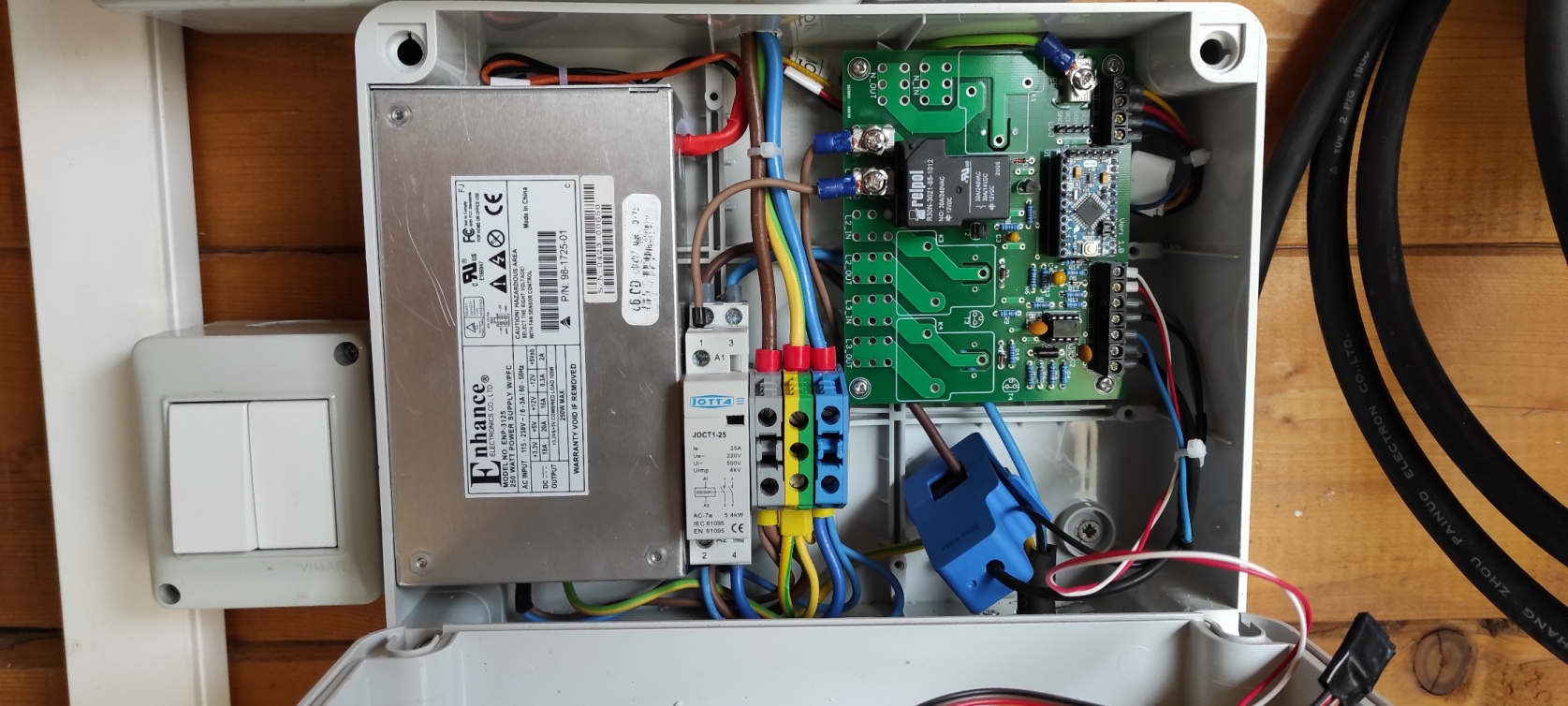
Please note that anything above 20A will need passive and active cooling for such small relays. I will add more information later about how this could be done. But we strongly advise you not to use relays for anything above 20A. Instead please use correctly rated 4 pole contactor.
Update: 10/10/2021
Power supply alternative
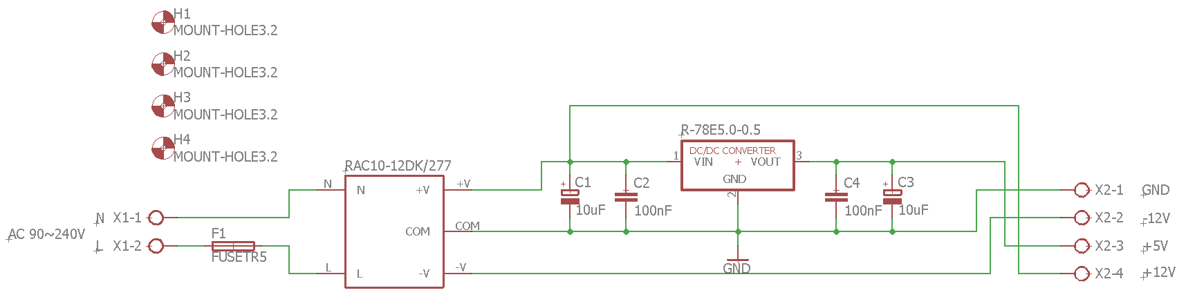
It seems that Mean Well PT-45B power supply is no longer easily sourceable. Even if you can find it sold locally, the price seems to be doubled in very short period of time. So I was looking for simple and cheap alternatives. One of such alternatives I am sharing below. It is very simple and can be built by using just a few components. Please note, that such power source is not suitable, if you are using Lolin Wifi board connected to your EVSE, as it's output is not strong enough to keep Lolin board powered up.
Part list for power supply:
AC-DC Converter - RECOM RAC10-12DK/277 (2 outputs: +12V and -12V)
DC-DC Converter - RECOM R-78E5.0-0.5 (single output of 5V 0.5A)
C1, C3 - 2x Capacitors 10uF
C2, C4 - 2x Capacitors 100nF
F1 - Fuse (TR5 type if you are using my PCB design)
X1, X2, X3 - 3x DG301 (XY306) 2 Position Screw Terminal Block (only if you are using my PCB design)
Power supply wiring diagram and Gerber files for PCB manufacturing can be found bellow:

|
EVSE_PSU_board.zip Size : 32.903 Kb Type : zip |
© Copyright EV-OLUTION