DIY cheap CAN logger bridge
This time I am sharing a very cheap solution for CAN message logging on a Nissan LEAF, and probably many other vehicles. Also it can be used as a bridge on the existing CAN line. In such way you not only can log messages, but also you can detect what exact messages vehicle module is sending.
The design is very simple. For controller I used Chinese made STM32F407VET6 Black Developing Board. And for CAN modules I used MCP2515 boards. You probably wonder why I haven't used STM32F407 internal CAN. It's because I wrote a firmware using Arduino IDE, and MCP2515 has a very good library and many examples, which makes programing much easier.
UPDATE: There is two versions of this CAN logger/bridge solution.
'Version 1' transmitting all CAN data on Serial communication port at speed of 921600 bit/s, so logging must be done on your computer. This way CAN bridge works in fastest way possible. It becomes fully functional in just 5 milliseconds after board is powered up.
'Version 2' logs the CAN data on SD card, so no additional hardware is required. But this solution has it's own limitations. It is not recommended to use 'Version 2' solution as a CAN bridge. It is recommended to use it only as a logger. Due to SD card write latency there is random delays in CAN message transmission, which might affect safety of vehicle or even trigger some fault codes. Also it takes about 230 ms for controller to get ready for work. So power supply would have to be applied first for CAN bridge/logger device before CAN line gets active.
So lets start from 'Version 1'
First of all you must upload firmware to STM32F407VET6 Black Developing Board. Easiest way to upload it is to use ST-Link or J-link programmers. I would strongly recommend to go for original ones instead of Chinese clones. As they are cheap enough and give way less problems while in use. You can get genuine J-Link EDU mini or ST-Link for about 20 Euros. So why to bother about clones? Also you can upload firmware just by using USB cable, but for this you will need to download ST software, drivers and do some configurations. I will not go in to details of how to do that. Please do bit of research on your own.
Firmware for 'Version 1' can be found bellow:

|
CAN_Bridge_with_Serial_921600.rar Size : 28.266 Kb Type : rar |
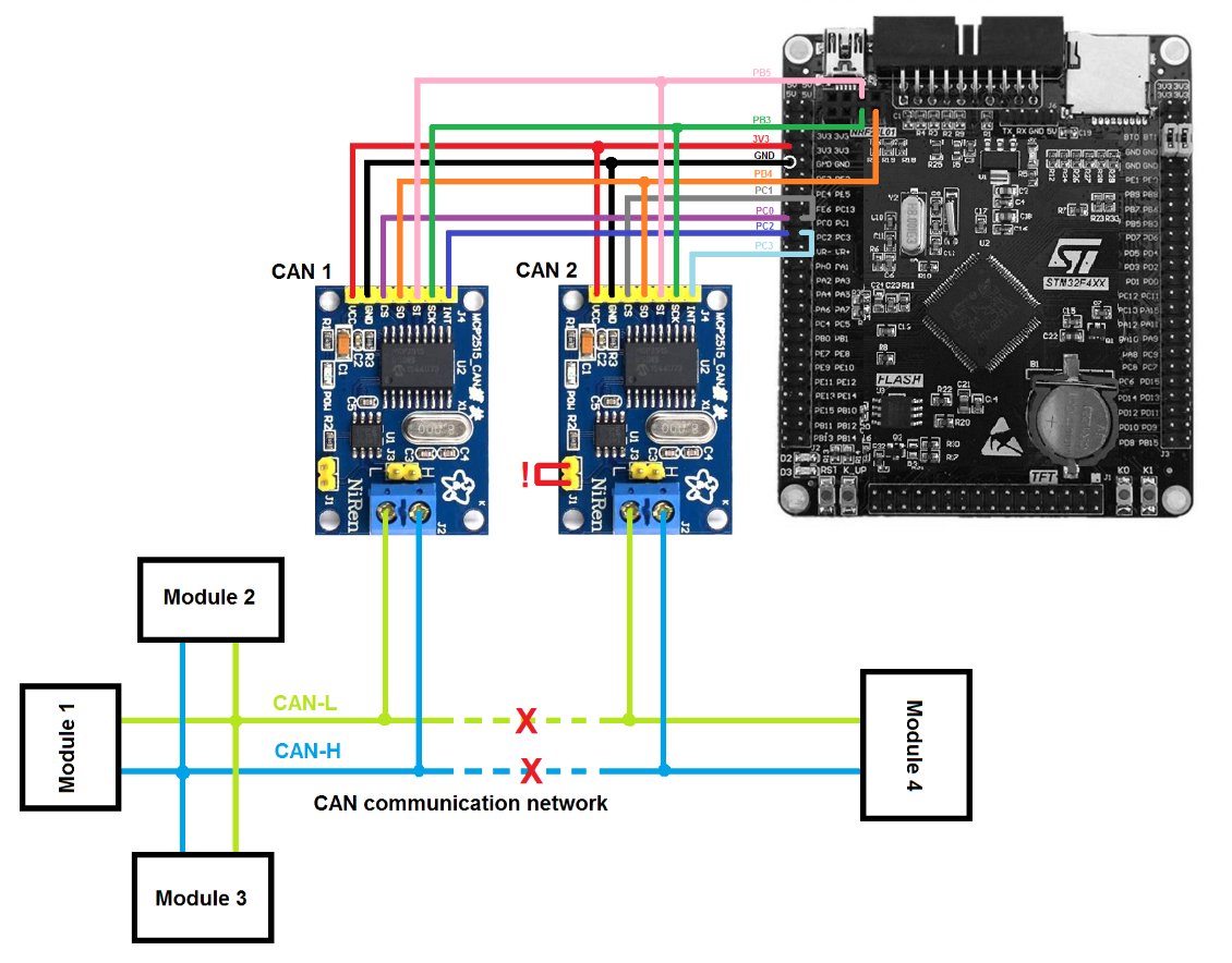
Once you done with firmware uploading, you must connect MCP2515 modules and USB to TTL converter to the controller exactly same as it's showed in diagram. To power controller board you can use existing mini USB connector on the board or use 12V to 5V inverter and 5V pins on the board (not shown in diagram).
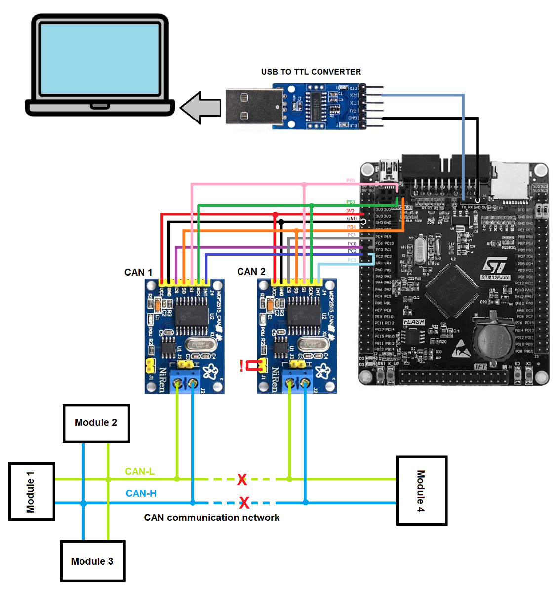
Bridge mode works in very simple way. If CAN 1 module receives a message, controller transmits it on Serial communication port and also CAN 2 module sends same message to CAN network. If CAN 2 module receives a message, controller again transmits it on Serial port and also passes to CAN 1 module. If you going to use it in a bridge mode, make sure you cut CAN line between connection of two CAN modules. Otherwise you will end up with CAN 1 and CAN 2 modules repeating exactly same message over and over again, which will make CAN network to malfunction.
If you just want to log the data on CAN network without using a bridge mode, then you can just connect CAN 1 module to CAN network on it's own and leave CAN 2 disconnected.
To log the transmitted data on Serial port you must use some kind of terminal logging software. Best software for this purpose is Realterm. And the best thing, it's completely free. But I strongly suggest you to donate to the developers so they can continue their great work.
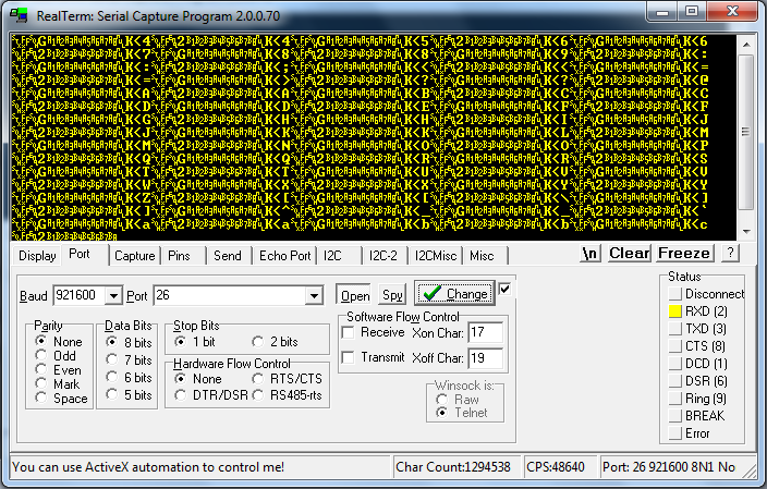
I personally use Realterm version 2.0.0.70. So all next "how to" information will be for this version. Once you got your USB to TTL converter drivers installed on your computer, plug it in and open Realterm program. Once it's opened, you must chose correct port. Press "Port" window, then chose correct COM port of your USB to TTL converter. Then set "Baud" to 921600 and press "Change" button to save changes. If your CAN bridge/logger is connected to CAN line and USB to TTL converter, and CAN network is active, you will see some data in terminal window. That means everything is working as it should.
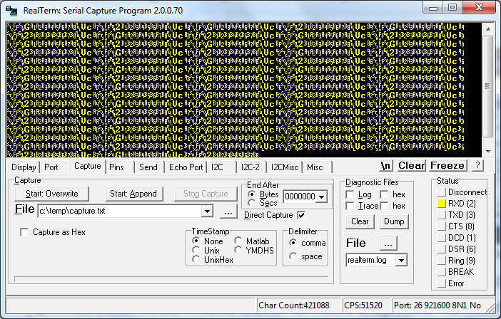
Now to get any useful data, we must capture it. Press on "Capture" window. Change File location to your preferred location of you log file. Make sure "Capture as Hex" is left unmarked. Also make sure "Direct Capture" is marked. If you want you can limit the size of log file by changing "End After" field settings. Once you ready to start logging CAN data, just press "Start:Overwrite" button. And when you want to stop it, press "Stop Capture" button. Be aware that log file becomes very very large after just a few minutes. So it is not recommended to leave logging for prolonged periods of time.
Logged data is saved in a binary format, and you will have to use some kind of binary viewer to see human readable data. For example my favorite tool for this is HxD Hexeditor.
Find log file, but do not open it with a standard text viewer. open it with binary viewer, such as Hexeditor. Once you open the log file in binary viewer, set it to show 16 Bytes per row.
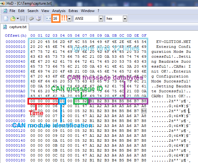
Make sure you set 16 Bytes per row (orange mark in a picture) in your binary viewer tool. If you started logging before you powered CAN bridge/logger, please ignore first 12 lines. Each line after that represents new CAN message log. First four Bytes (red mark in a picture) represents time in milliseconds in hexadecimal format from microcontroller start till message received. For example 00 00 00 05 translates as 5 milliseconds. If you don't know how to do hexadecimal to decimal conversion, you can just simply use online convertor: https://www.binaryhexconverter.com/hex-to-decimal-converter
CAN module identification Byte (blue mark in a picture) follows after four time Bytes. 01 means message received to CAN 1 module, 02 means message received to CAN 2 module. After which 00 always follows.
Bytes 6 and 7 (green mark in a picture) represents received CAN message ID number. 05 32 means that message ID is 532.
Bytes from 8 to 15 (violet mark in a picture) represents CAN message data bytes.
If you need this data log in text format, most binary viewers have an option to export opened file to different formats, including the text one.
----------------------------------------------------------------------------------
That's it for a 'Version 1', now lets go to 'Version 2'
First of all before going into technical stuff of 'Version 2' I want you to know that this device will have some limitations:
- Logging is limited to maximum of 10 minutes or 600000 can messages, which ever comes first. Although CAN bridge will stay functional after limit has been reached to make sure CAN network is not affected and stays fully functional.
- Logged data is also saved in binary format, and you will have to use some kind of binary viewer to see human readable data.
- There are some delays between data logging and also microcontroller starting. So you must power up logger first before waking up the CAN network.
- Communication speed is 500kbps. And it only works with standard frame message format (11 identifier bits).
Please upload firmware to STM32F407VET6 Black Developing Board.
Firmware for 'Version 2' can be found bellow:
|
|
BETA_CAN_bridge_SD_logger.rar Size : 48.597 Kb Type : rar |
Connect your hardware as shown in the picture bellow. You must connect MCP2515 modules to the controller exactly same as it's showed in diagram. To power controller board you can use existing mini USB connector on the board or use 12V to 5V inverter and 5V pins on the board (not shown in diagram).
Make sure you power STM32 board first before CAN network gets active. As there is about 230ms delay till STM32 board gets ready and transmits data. Also make sure micro SD card is present in it's socket, otherwise CAN bridge would not start working until you add micro SD card. If one of CAN modules is not connected properly or malfunctions while initializing, D3 LED will lit up.
After you powered your board and CAN logging begun, controller will create a data file. Every file will contain maximum of 30000 CAN messages. There will be up to 20 of such files.
To safely stop microSD card you must press K0 button on STM32F407 board before attempting to remove it. After you pressed K0 button you will notice that LED D2 changes it's flashing pattern (unless 10 minutes have passed from controller power up or reset). That indicates that it's safe to remove microSD card. Also you must only use empty microSD card formatted to FAT system. Otherwise some instabilities might happen.
Once you get your card out and put in your computer, you must use binary viewer tool to be able to see what's inside the generated .dat files. Bellow you will find example of generated data file opened in HxD:
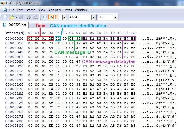
Make sure you set 16 Bytes per row (orange mark in a picture) in your binary viewer tool. Each line represents new CAN message log. First four Bytes (red mark in a picture) represents time in milliseconds in hexadecimal format from microcontroller start till message received. For example 01 DD translates as 477 milliseconds. If you don't know how to do hexadecimal to decimal conversion, you can just simply use online convertor: https://www.binaryhexconverter.com/hex-to-decimal-converter
CAN module identification Byte (blue mark in a picture) follows after four time Bytes. 01 means message received to CAN 1 module, 02 means message received to CAN 2 module. After which 00 always follows.
Bytes 6 and 7 (green mark in a picture) represents received CAN message ID number. 05 32 means that message ID is 532.
Bytes from 8 to 15 (violet mark in a picture) represents CAN message data bytes.
If you need this data log in text format, most binary viewers have an option to export opened file to different formats, including the text one.
----------------------------------------------------------------------------------
If you get any problems, or have some suggestions regarding this project, please feel free to contact us.
Now the legal bit. This project should not be used in a vehicle on a public roads. It is strictly only to be used as a experimental equipment. I will not take any responsibility for property damage or injury caused by using information provided above. If you don't feel confident with taking on such project, then don't, because failures and mistakes can be very expensive.
I hope you found something useful here. Soon I might share firmware for same hardware to be used as a man-in-the-middle solution for Nissan LEAF battery swaps. So keep checking our Facebook page or this website.
© Copyright EV-OLUTION